2.
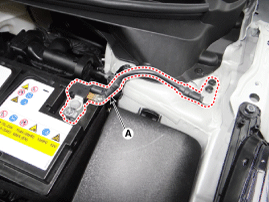
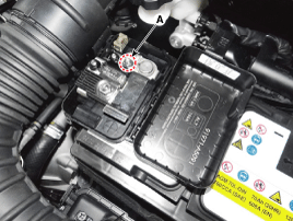
Disconnect the negative (-) battery terminal (A).
Negative (-) battery terminal tightening nut :
4.0 ~ 6.0 N.m (0.4 ~ 0.6 kgf.m, 3.0 ~ 4.4 lb-ft)
After disconnecting then reconnecting the battery negative cable, reset some parts that require the reset procedures.
(Refer to Body Electrical System – "General Information")
Turn the ignition switch OFF.
Disconnect the negative (-) battery terminal (A).
Negative (-) battery terminal tightening nut :
4.0 ~ 6.0 N.m (0.4 ~ 0.6 kgf.m, 3.0 ~ 4.4 lb-ft)
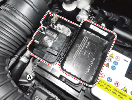
Disconnect the positive (+) battery terminal (A).
Positive (+) battery terminal tightening nut:
7.8 ~ 9.8 N.m (0.8 ~ 1.0 kgf.m, 5.2 ~ 8.7 lb-ft)
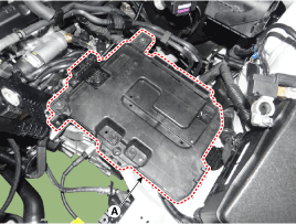
Remove the air cleaner.
(Refer to Engine Mechanical System - "Air Cleaner")
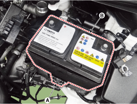
Remove the battery mounting bracket (A) after loosening the mounting bolt.
Remove the battery (B).
Battery mounting bracket mounting bolt :
8.8 ~ 13.7 N.m (0.9 ~ 1.4 kgf.m, 6.5 ~ 10.1 lb-ft)
Remove the battery.
(Reter to Engine Electrical System - "Battery")
Disconnect the ECM Connector (A).
Remove the mounting bolts and nut, and then remove the ECM bracket assembly (B).
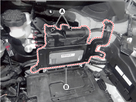
Remove the battery tray (A) after loosening the mounting bolts
Battery tray mounting bolt:
8.8 ~ 13.7 N.m (0.9 ~ 1.4 kgf.m, 6.5 ~ 10.1 lb-ft)
Install in the reverse order of removal.
When installing the battery, fix the mounting bracket on the tray correctly.
After disconnecting then reconnecting the battery negative cable, reset some parts that require the reset procedures.
(Refer to Body Electrical System - "General Information")
When installing the battery, fix the mounting bracket on the tray correctly.
ISG (Idle stop & go) system equipped vehicle uses the AGM battery only. Installing a flooded battery may potentially lead to engine electrical trouble or ISG system error.
Replace with an AGM battery of the same capacity.
Ensure that an AGM battery is fitted.
In all cases, an AGM battery must be installed and registered in the vehicle for the ISG function to work perfectly.
After replacing with a new battery, the vehicle must stand for at least 4 hours with the ignition switch OFF, doors closed and hood switch OFF.
ISG system stabilization may take 4 hours after installing a new battery.
After standing for 4 hours, the ISG function will operate with 2 cranks by the user.
However, for the first 25 times, the ISG function can operate regardless of ISG system stability for ISG function operation check.
Do not open the AGM battery.
The AGM battery must not be opened under any circumstances as the introduction of oxygen from the air will cause the battery to lose its chemical equilibrium and become non-operational.
In general, vehicle battery charging system has three forms.
Constant current charge: The battery voltage gradually rises by charging at a constant current setting. If charging current and time are not managed correctly, the battery may be overcharged. Therefore, stop charging after confirming the completion of charging.
General charge: Charging the battery for a long time with low current
Quick charge: Charging the battery for a short time with high current
Constant voltage charge: The battery charging current gradually reduces by charging at a constant voltage setting.
If the battery is charged directly at the battery terminals on vehicles with battery sensor, misinterpretations of battery condition may occur, and under certain circumstances, unwanted 'Check Control' message or faulty memory can be prompted.
When recharging is finished, let the battery stand for over 10 hours at normal temperature for battery stabilization.
Check the battery voltage and status by using a battery tester.
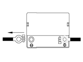
Move back and forth to check if the battery terminals (A) are loose or corroded. Clean any corroded terminals.
If the battery positive connection is loose, disconnect the ground (GND) cable first before attempting to remove or tighten the positive connection to prevent personal injury.
If the battery clamp on positive (+) battery terminal is not seated securely:
Turn ignition switch OFF and disconnect the battery negative (-) terminal.
Tighten battery clamp (A) on positive (+) battery terminal.
Positive (+) battery terminal:
7.8 ~ 9.8 N.m (0.8 ~ 1.0 kgf.m, 5.8 ~ 7.2 lb-ft)
If the battery clamp on negative (-) battery terminal is not seated securely:
Tighten battery clamp (A) on negative (-) battery terminal.
Negative (-) battery terminal:
4.0 ~ 6.0 N.m (0.4 ~ 0.6 kgf.m, 3.0 ~ 4.4 lb-ft)
Check the battery for damage or deformation. If severe damage, deformation or leakage is found, replace the battery.
[Using an Ammeter]
Turn the all electric devices OFF, and then turn the ignition switch OFF.
Close all doors except the engine hood, and then lock all doors.
Disconnect the hood switch connector.
Close the trunk lid.
Close the doors or remove the door switches.
Wait a few minutes until the vehicle’s electrical systems go to sleep mode.
For an accurate measurement of a vehicle parasitic current, all electrical systems should go to sleep mode. (It takes at least one hour or at most one day.) However, an approximate vehicle parasitic current can be measured after 10 - 20 minutes.
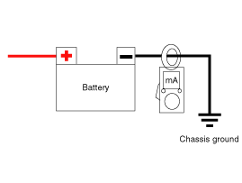
Connect an ammeter in series between the battery (-) terminal and the ground cable, and then disconnect the clamp from the battery (-) terminal slowly.
Be careful that the lead wires of an ammeter do not come off from the battery (-) terminal and the ground cable to prevent the battery from being reset. In case the battery is reset, connect the battery cable again, and then start the engine or turn the ignition switch ON for more than 10 sec. Repeat the procedure from No. 1.
To prevent the battery from being reset during the inspection,
Connect a jump cable between the battery (-) terminal and the ground cable.
Disconnect the ground cable from the battery (-) terminal.
Connect an ammeter between the battery (-) terminal and the ground cable.
After disconnecting the jump cable, read the current value of the ammeter.
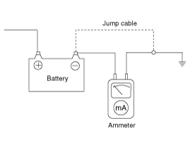
Read the current value of the ammeter.
If the parasitic current is over the limit value, search for abnormal circuit by removing a fuse one by one and checking the parasitic current.
Reconnect only the fuse suspected of parasitic current and search for the problematic unit by removing the components connected to the circuit one by one until the parasitic draw drops below limit value.
Limit value (after 10-20 min.) : Below 50mA
[Using a Clamp type Ammeter]
Turn the all electric devices OFF, and then turn the ignition switch OFF.
Close all doors except the engine hood, and then lock all doors.
Disconnect the hood switch connector.
Close the trunk lid.
Close the doors or remove the door switches.
Wait a few minutes until the vehicle’s electrical systems go to sleep mode.
For an accurate measurement of a vehicle parasitic current, all electrical systems should be in sleep mode. (It takes at least one hour or at most one day.) However, an approximate vehicle parasitic current can be measured after 10-20 minutes.
Install the clamp type ammerter on battery negative (-) terminal.
Read the current value of the ammeter.
If the parasitic current is over the limit value, search for abnormal circuit by removing a fuse one by one and checking the parasitic current.
Reconnect only the fuse suspected of parasitic current and search for the problematic unit by removing the components connected to the circuit one by one until the parasitic draw drops below limit value.
Limit value (after 10-20 min.) : Below 50mA
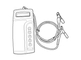
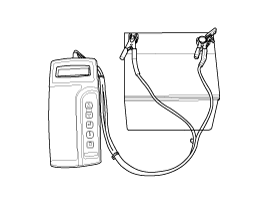
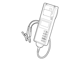
By using the Micro 570 Analyzer, the charging and starting systems including the battery, starter and alternator can be tested.
Due to the possibility of personal injury, always take extreme caution and wear appropriate eye protection when working on batteries.
When charging the battery based on test result, it must be fully charged.
When retesting after charging the battery, test after the surface voltage of the battery have subsided for an accurate test result. (Refer to "Battery Test Result" below.)
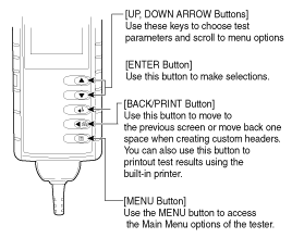
The Micro 570 buttons on the keypad provide the following functions:
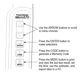
Connect the tester to the battery.
Red clamp to positive (+) battery terminal
Black clamp to negative (-) battery terminal
Connect clamps securely. If "CHECK CONNECTION" message is displayed on the screen, reconnect clamps securely.
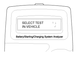
The tester will ask if the battery is connected "IN-VEHICLE" or "OUT-OF-VEHICLE". Make your selection by pressing the arrow buttons; then press ENTER.
Select CCA and press the ENTER button.
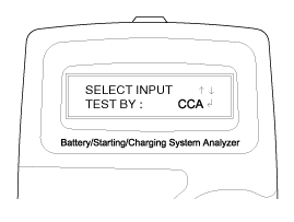
CCA : Cold cranking amps, is an SAE specification for cranking batteries at -0.4°F (-18°C).
Set the CCA value displayed on the screen to the CCA value marked on the battery label by pressing up and down buttons and pressing ENTER.
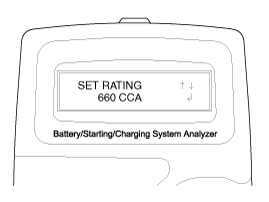
The battery ratings (CCA) displayed on the tester must be identical to the ratings marked on battery label.
The tester will conduct battery test.
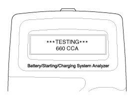
The tester displays battery test results including voltage and battery ratings.
Refer to the following table and take the appropriate action as recommended by the Micro 570.
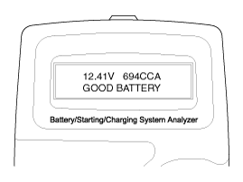
Result On Printer | Remedy |
GOOD BATTERY | No action is required. |
GOOD - RECHARGE | Battery is in a good state. Recharge the battery for use. ● Follow the instruction below when charging and retesting the battery, otherwise the test result may be inaccurate. (See ‘Charging and Retesting after charging battery’ below.) |
CHARGE & RETEST | Battery is not charged properly. - Charge and test the battery again. ● Follow the instruction below when charging and retesting the battery, otherwise the test result may be inaccurate. (See ‘Charging and Retesting after charging battery’ below.) |
REPLACE BATTERY | Replace battery and recheck the charging system. - Improper connection between battery and vehicle cables may prompt "REPLACE BATTERY" message. Retest the battery after removing cables and connecting the tester to the battery terminal directly prior to replacing the battery. |
BAD CELL-REPLACE | Charge and retest the battery. - If "REPLACE BATTERY" is prompted on Micro 570, replace the battery and recheck the charging system. |
Charging battery
Set battery charger to ‘Auto Mode’ (the Mode that charging current drops as the battery charges) and charge battery until charging current drops down close to zero or the charger alerts with an alarm when charging is complete.
(Minimum charging time recommended: More than 3 hours in Auto Mode explained above)
If battery is not fully charged, battery surface voltage will be high while the amount of current charged (CCA) in battery is low. If the battery is tested in this condition, the tester may misjudge that battery sulfation has occurred as the level of current in battery is too low in comparison with battery voltage.
* Surface voltage: When battery is charged electrolyte temperature increases and chemical reaction become active resulting in an excessive increase of battery voltage.
It is known that it takes approximate one day to subside this increased surface voltage completely.
Testing battery after charging
Do not test the battery immediately after charging. Test the battery after the battery surface voltage has subsided as instructed in the following procedure.
When battery charging is complete, install the battery to the vehicle.
Turn IG ON, turn on the headlamps at low beam, and wait for 5 minutes. (Discharge for 5 minutes.)
Turn off the headlamps at IG ON, and wait for 5 minutes. (Wait for 5 minutes.)
Remove +, - cables from the battery and test battery.
Whenever filing a claim for battery, the print out of the battery test results must be attached.
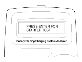
Starter Test Procedure
After the battery test, press ENTER immediately for the starter test.
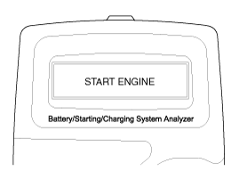
Start the engine.
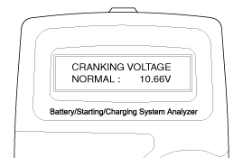
Cranking voltage and starter test results will be displayed on the screen.
Refer to the following table and take the appropriate action as recommended by the Micro 570.
Result On Printer | Remedy |
CRANKING VOLTAGE NORMAL | System shows a normal starter draw. |
CRANKING VOLTAGE LOW | Cranking voltage is lower than normal level. - Check starter. |
CHARGE BATTERY | The battery level is too low for the test. - Charge the battery and retest. |
REPLACE BATTERY | Replace battery. - If the vehicle cannot be started even though "GOOD BATTERY" is displayed, check wiring for open circuit, battery cable connection and starter, and repair or replace as necessary. - If the engine does not crank, check fuel system. |
When testing a vehicle with an old diesel engine, the test result may not be favorable if the glow plug is not heated. Conduct the test after warming up the engine for 5 minutes.
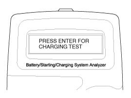
Charging System Test Procedure
Press ENTER to begin charging system test.
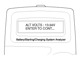
The tester displays the actual voltage of alternator.
Press ENTER to continue.
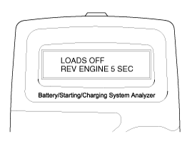
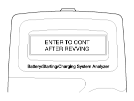
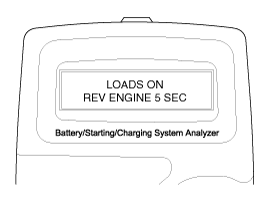
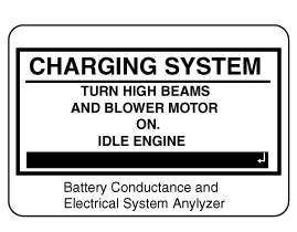
Turn off all electrical loads and rev up the engine for 5 seconds by pressing the accelerator pedal. (Follow the instructions on the screen)
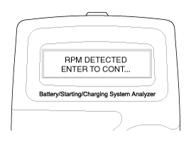
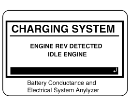
The message that engine RPM is detected will be displayed on the screen. Press ENTER to continue.

If the engine RPM is not detected, press ENTER after revving up the engine.
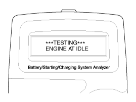
The tester will conduct charging system test during loads off.

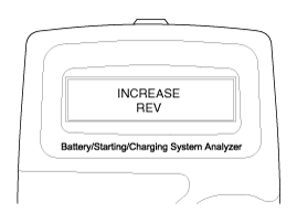
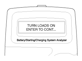
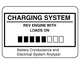
Rev up the engine with the electrical loads on.
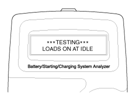
The tester will conduct charging system test during loads on.
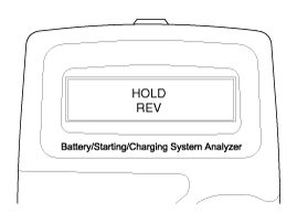
Rev up the engine for 5 seconds by pressing the accelerator pedal. (Follow the instructions on the screen.)


The message that engine RPM is detected will be displayed on the screen. Press ENTER to continue.
If the engine RPM is not detected, press ENTER after revving up the engine.

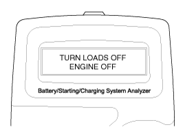
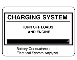
Turn off electrical loads (air conditioner, lamps, audio and etc). Turn the engine off.
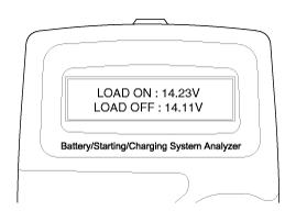
Charging voltage and charging system test results will be displayed on the screen.
Shut off the engine and disconnect the tester clamps from the battery. Refer to the following table and take the appropriate action as recommended by the Micro 570.
Result On Printer | Remedy |
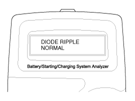
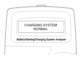
CHARGING SYSTEM NORMAL / DIODE RIPPLE NORMAL | Charging system is normal. |
NO CHARGING VOLTAGE | Alternator does not supply charging current to battery. - Check belts, connection between alternator and battery and replace belts, or cable or alternator as necessary. |
LOW CHARGING VOLTAGE | Alternator does not supply charging current to battery and electrical load to system fully. - Check belts and alternator and replace as necessary. |
HIGH CHARGING VOLTAGE | The voltage from alternator to battery is higher than normal limit during voltage regulation. - Check connection and ground and replace regulator as necessary. - Check electrolyte level in the battery. |
EXCESS RIPPLE DETECTED | One or more diodes in the alternator is not functioning properly. - Check alternator mounting and belts and replace as necessary. |
The MDX-670P battery conductance and electrical system analyzer tests batteries as well as starting and charging systems of the vehicle.
It displays the test results in seconds and features a built-in printer to provide a copy of the results.
Because of the possibility of personal injury, always use extreme caution and appropriate eye protection when working with batteries.
When charging a battery based on test result, it must be fully charged. For an accurate test result, test the battery when the battery surface voltage has subsided completely after charging it. (Refer to Battery Test Results below.)
When testing a vehicle with an old diesel engine, the test result may not be favorable if the glow plug is not heated. Conduct the test after warming up the engine for 5 minutes.
Connect the red clamp to the positive (+) terminal and the black clamp to the negative (–) terminal.
For a proper connection, rock the clamps back and forth. The tester requires that both sides of each clamp be firmly connected before testing. A poor connection may prompt CHECK CONNECTION or WIGGLE CLAMPS message. If the message appears, clean the terminals and reconnect the clamps.
Scroll to and select IN VEHICLE or OUT OF VEHICLE for a battery not connected to a vehicle.
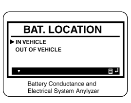
Following an IN VEHICLE test you will be prompted to test the starting and charging systems.
Scroll to and select REGULAR FLOODED, AGM FLAT PLATE, or AGM SPIRAL where applicable.
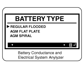
For a vehicle equipped with ISG function, select the AGM FLAT PLATE.
Scroll to and select the battery’s rating system.
In most cases, the CCA value is marked on the battery label, but sometimes it is substituted with the EN or SEA value. Select any of them.
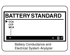
CCA: Cold Cranking Amps, as specified by SAE, is the most common rating for cranking batteries at 0°F (-17.8°C).
EN: Europe-Norm
SAE: Society of Automotive Engineers, the European labeling of CCA
Set the selected rating value displayed on the screen to the value marked on the battery label by pressing up and down arrow buttons.
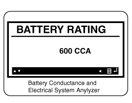
Press ENTER to start test.
After several seconds, the tester will display the battery condition and the measured voltage. The tester will also display the battery rating and the rating units.
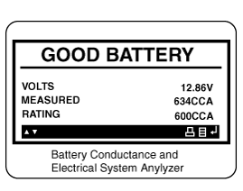
Result On Printer | Remedy |
GOOD BATTERY | No action is required. |
GOOD - RECHARGE | Battery is in a good state. Recharge the battery for use. ● Follow the instruction below when charging and retesting the battery, otherwise the test result may be inaccurate. (See ‘Charging and Retesting after charging battery’ below.) |
CHARGE & RETEST | Battery is not charged properly. - Charge and test the battery again. ● Follow the instruction below when charging and retesting the battery, otherwise the test result may be inaccurate. (See ‘Charging and Retesting after charging battery’ below.) |
REPLACE BATTERY | Replace battery and recheck the charging system. - Improper connection between battery and vehicle cables may prompt "REPLACE BATTERY" message. Retest the battery after removing cables and connecting the tester to the battery terminal directly prior to replacing the battery. |
BAD CELL - REPLACE | Charge and retest the battery. - If "REPLACE BATTERY" is prompted on MDX-670P Analyzer, replace the battery and recheck the charging system. |
Charging battery
Set battery charger to ‘Auto Mode’ (the Mode that charging current drops as the battery charges) and charge battery until charging current drops down close to zero or the charger alerts with an alarm when charging is complete. (Minimum charging time recommended: More than 3 hours in Auto Mode explained above)
If battery is not fully charged, battery surface voltage will be high while the amount of current charged (CCA) in battery is low. If the battery is tested in this condition, the tester may misjudge that battery sulfation has occurred as the level of current in battery is too low in comparison with battery voltage.
* Surface voltage: When battery is charged, electrolyte temperature increases and chemical reaction becomes active resulting in an excessive increase in battery voltage.
It is known that it takes approximate one day to subside this increased surface voltage completely.
Testing battery after charging
Do not test the battery immediately after charging. Test the battery after the battery surface voltage has subsided as instructed in the following procedure.
When battery charging is complete, install the battery to the vehicle.
Turn IG ON, turn on the headlamps at low beam, and wait for 5 minutes. (Discharge for 5 minutes.)
Turn off the headlamps at IG ON, and wait for 5 minutes. (Wait for 5 minutes.)
Remove +, - cables from the battery and test battery.
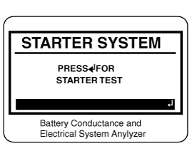
For an in-vehicle test, the display alternates between the test results and the message “PRESS FOR STARTER TEST.
Before starting the test, inspect the alternator drive belt. A belt that is glazed or worn, or lacks the proper tension, will prevent the engine from achieving the rpm levels needed for the test.
Press the ENTER button to proceed with the starter test.
Start the engine when prompted.
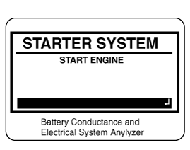
The tester displays the status of the starter system, cranking voltage, and cranking time in milliseconds.
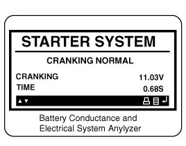
Result On Printer | Remedy |
CRANKING VOLTAGE NORMAL | System shows a normal starter draw. |
CRANKING VOLTAGE LOW | Cranking voltage is lower than normal level. - Check starter. |
CHARGE BATTERY | The battery level is too low for the test. - Charge the battery and retest. |
REPLACE BATTERY | Replace battery. - If the vehicle cannot be started even though "GOOD BATTERY" is displayed, check wiring for open circuit, battery cable connection and starter, and repair or replace as necessary. - If the engine does crank, check fuel system. |
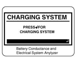
For an in-vehicle test, the display alternates between the test results and the message “PRESS FOR CHARGING TEST.
Step 3: Charging System Test
Press the ENTER button to proceed with the charging test.
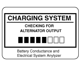
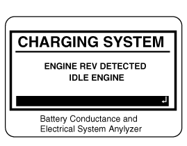
Rev up the engine with loads off. (Following the on-screen prompts)

The message that engine RPM is detected will be displayed on the screen. Idle the engine.
Turn on electrical loads (air conditioner, lamps, audio and etc). Press ENTER to continue.
Turn on electrical loads (air conditioner, lamps, audio and etc). Press ENTER to continue.
The message that engine RPM is detected will be displayed on the screen. Idle the engine.
Turn off loads and engine.
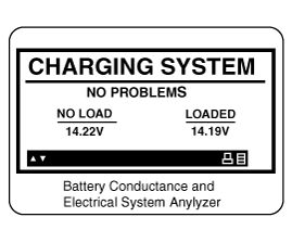
The status of the Charging System is displayed at the end of the procedure.
Result On Printer | Remedy |
NO PROBLEMS | System is showing normal output from the alternator. |
NO OUTPUT | No alternator output detected. - Check all connections to and from the alternator, especially the connection to the battery. If the connection is loose or heavily corroded, clean or replace the cable and retest. - If the belts and connections are in good working condition, replace the alternator. (Older vehicles use external voltage regulators, which may require replacement of the voltage regulator only.) |
LOW OUTPUT | Alternator does not supply charging current to battery and electrical load to system fully. - Check belts and alternator and replace as necessary. |
HIGH OUTPUT | The voltage from alternator to battery is higher than normal limit during voltage regulation. - Check connection and ground and replace regulator as necessary. - Check electrolyte level in the battery. |
EXCESSIVE RIPPLE | The voltage from alternator to battery is higher than normal limit during voltage regulation. - Check alternator mounting and belts and replace as necessary. |
CHARGE BATTERY | The starter voltage is low and the battery is discharged. Fully charge the battery and repeat the starter system test. |
REPLACE BATTERY | Battery must be replaced before the starting system can be tested. |
Press the BACK/PRINT button to print the test results or MENU to return to the Options Menu.
Make sure that the ignition switch and all accessories are turned OFF.
Disconnect the battery cables (negative first).
Remove the battery from the vehicle.
Care should be taken in the event the battery case is cracked or leaking, to protect your skin from the electrolyte.
Heavy duty rubber gloves (not the household type) should be worn when removing the battery.
Inspect the battery tray for damage caused by the loss of electrolyte. If acid damage is present, it will be necessary to clean the area with a solution of clean warm water and baking soda. Scrub the area with a stiff brush and wipe off with a cloth moistened with baking soda and water.
Clean the top of the battery with the same solution as described above.
Inspect the battery case and cover for cracks. If cracks are present, the battery must be replaced.
Clean the battery posts with a suitable battery post tool.
Clean the inside surface of the terminal clamps with a suitable battery cleaning tool. Replace damaged or frayed cables and broken terminal clamps.
Install the battery in the vehicle.
Connect the cable terminals to the battery post, making sure tops of the terminals are flush with the tops of the posts .
Tighten the terminal nuts securely.
Coat all connections with light mineral grease after tightening.
When batteries are being charged, an explosive gas forms beneath the cover of each cell. Do not smoke near batteries being charged or which have recently been charged. Do not break live circuit at the terminals of batteries being charged.
A spark will occur when the circuit is broken. Keep open flames away from battery.
