3.
Is the problem found?

▶ Repair the trouble causing part and go to "Verification of Vehicle Repair".

▶ Go to "Ground Circuit Inspection".
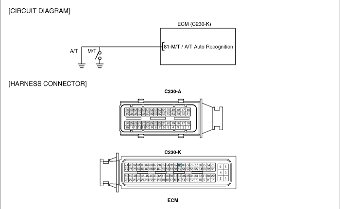
Because both A/T and M/T fuel control map is inputted in one type of ECM and selecting option is possible, one type is applied to both A/T and M/T option.When ECM is installed to vehicle, A/T and M/T recognition is performed by ECM automatically as checking whether ground line(ECM connector C230-K terminal 81) is grounded or opened.(A/T and M/T recognition is performed every IG KEY ON process.) If A/T, M/T recognition is not fulfilled well or any error occurs during the process, engine power generation is not sufficient and glow lamp on cluster blinks.
A/T : ECM connector C230-K terminal 81 is grounded
M/T : ECM connector C230-K terminal 81 is opened(no wiring exists)
P1587 is set when ECM is recognized as 1)A/T but CAN communication signal is not transmitted from TCM 2)M/T but CAN communication signal is transmitted from TCM. After checking if A/T, M/T auto recognition terminal is correct for each vehicle option, if no problem is detected, check poor connection in CAN communication circuit or CAN communication problem of TCM.
Item | Detecting Condition | Possible Cause | ||
DTC Strategy | ● Voltage monitoring | ● A/T, M/T recognition terminal circuit ● CAN communication line circuit ● TCM component failure ● ECM component failure | ||
Enable Conditions | ● Engine running | |||
Threshold Value | ● TCM signal is not detected at A/T vehicle TCM signal is detected at M/T vehicle | |||
Diagnostic Time | ● 1.0 sec. | |||
Fail Safe | Fuel cut | NO | ● Glow Lamp blinks. | |
EGR Off | NO | |||
Fuel Limit | NO | |||
Check Lamp | NO | |||
Electrical systems consist of a lot of harness and connectors, poor connection of terminals can cause various problems and damge of component.
Perform checking procedure as follows.
Check damage of harness and terminals : Check terminals for contact resistance, corrosion and deformation.
Check connecting condition of ECM and component connector : Check terminal seperation, damage of locking device and connecting condition between terminal and wiring.
Disconnect the pin which requires checking at male connector and insert it to the terminal at female connector for checking connecting condition. ( after checking, reconnect the pin at correct position. )
Is the problem found?
▶ Repair the trouble causing part and go to "Verification of Vehicle Repair".
▶ Go to "Ground Circuit Inspection".
IG KEY "OFF", ENGINE "OFF".
Disconnect ECM connector.
Check continuity between ECM connector(C230-K) terminal 81 and chassis ground.
Specification : Continuity (below 1.0Ω )
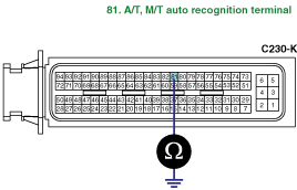
Is A/T, M/T auto recognition terminal grounded well?
▶ Go to "CAN communication line inspection".
▶ Repair poor connection or open in G15 ground point related circuit and go to "Verification of Vehicle Repair".
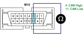
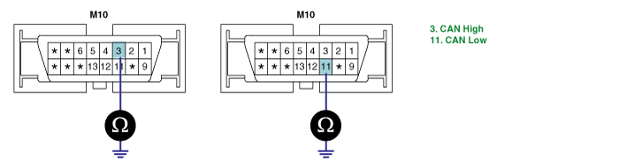
Check CAN BUS vertical resistance
IG KEY "OFF", ENGINE "OFF"
Measure the resistance between DLC terminal 3 and 11.
Disconnect ECM connector.
Measure the resistance between DLC terminal 3 and 11.
Specification : Both ECM and TCM are connected : 60 ± 3Ω
Both ECM and TCM are disconnected : 120 ± 3Ω
Is measured CAN BUS vertical resistance value within the specification?
▶ Go to "2. Check short to ground in CAN BUS" as follows.
▶ When measured resistances for both cases are below 10Ω : Repair short between one CAN BUS CAN and another one, and go to "Verification of Vehicle Repair".
▶ When measured resistances for both cases are 120Ω : Go to"4. CAN BUS continuity test"
▶ When measured resistances for both cases are infiniteΩ :Repair open in CAN communication circuit between DLC terminal box.When measured resistances for both cases are infiniteΩ :Repair open in CAN communication circuit between DLC terminal box.
Check short to ground in CAN BUS
IG KEY "OFF", ENGINE "OFF"
Disconnect ECM connector and TCM connector.
Check the continuity between DLC terminal 3 and chassis ground. (CAN HIGH)
Check the continuity between DLC terminal 11 and chassis ground. (CAN LOW)
Specification : Discontinuity (Infinite Ω)
Is CAN BUS insulated with ground correctly?
▶ Go to "3. Check short to battery in CAN BUS" as follows.
▶ Repair short to ground and go to "Verification of Vehicle Repair".
Check short to battery in CAN BUS
IG KEY "OFF", ENGINE "OFF"
Disconnect ECM connector and TCM connector.
IG KEY "ON"
Measure the voltage of DLC terminal 3.(CAN HIGH)
Measure the voltage of DLC terminal 11.(CAN LOW)
Specification : 0.0V~0.1V
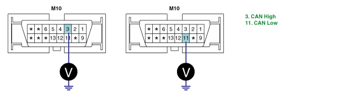
Is abnormal voltage detected with both connectors disconnected?
▶ Repair short to battery and go to "Verification of Vehicle Repair".
▶ Go to "4. CAN BUS continuity test" as follows.
CAN BUS continuity test
IG KEY "OFF", ENGINE "OFF"
Disconnect ECM connector and TCM connector.(Disconnect "CAN communication" related connectors.)
Check continuity between DLC terminal 3 and CAN HIGH terminal or each module.
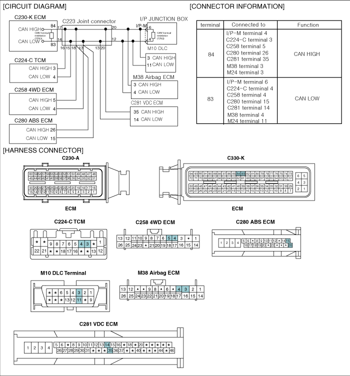
( CAN HIGH : ECM connector terminal 84, TCM connector terminal 3, ABS connector terminal 3, VDC connector terminal 35, 4WD ECM connector terminal 5, Airbag ECM connector terminal 3)
Check continuity between DLC terminal 11 and CAN LOW terminal or each module.
( CAN HIGH : ECM connector terminal 83, TCM connector terminal 4, ABS connector terminal 15, VDC connector terminal 14, 4WD ECM connector terminal 4, Airbag ECM connector terminal 4)
Specification : Continuity( below 1.0Ω )
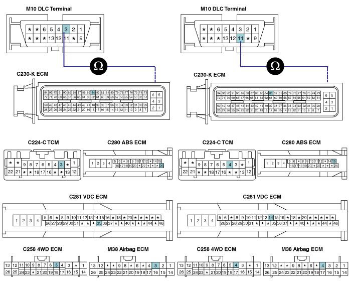
Is continuity of CAN BUS line confirmed?
▶ Go to "Component Inspection".
▶ Repair open in CAN communication line and go to "verification of Vehicle Repair".
CAN communication waveform inspection
IG KEY "OFF", ENGINE "OFF".
Connect 2 channel scope to DLC terminal 3(CAN HIGH) and 11(CAN LOW),
Connect only ECM connector to CAN BUS and turn IG KEY "ON".
Connect only TCM connector to CAN BUS and turn IG KEY "ON".
Specification : The waveform similar to the waveform above is displayed at "IG KEY "ON".
※ If both CAN High and Low signals are fixed at 2.5V or High signal is 3.5V and Low signal, this means communicaiton error of each module.
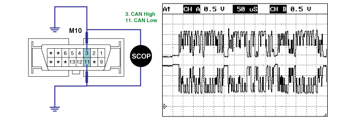
Is waveform similar to above waveform displayed?
▶ Go to "Verification of vehicle Repair.
▶ Replace the module from which abnormal waveform is outputted, and go to "Verification of Vehicle Repair".
After a repair, it is essential to verify that the fault is corrected.
After connecting Scantool select "DIAGNOSTIC TROUBLE CODES(DTCs)" mode.
Clear recorded DTC using Scantool.
Drive the vehicle within DTC "Enable conditions" in "General information".
After selecting "DIAGNOSTIC TROUBLE CODES(DTCs)" mode and check if DTC is recorded again.
Are any DTCs recorded ?
▶ Go to the DTC guide of recorded NO. in Scantool.
▶ System operates within specification.
