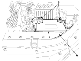
Remove the air duct and the battery(A) after disconnecting the terminals(B) from the battery.
Use fender covers to avoid damaging painted surfaces.
To avoid damage, unplug the wiring connectors carefully while holding the connector portion.
Mark all wiring and hoses to avoid misconnection.
Remove the air duct and the battery(A) after disconnecting the terminals(B) from the battery.

Remove the engine cover.
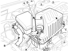
Remove the intake air hose and air cleaner assembly.
Disconnect the MAF connector(A).
Disconnect the breather hose(B) from air cleaner hose.
Remove the intake air hose and air cleaner assembly(C).
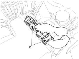
Disconnect the PCM connectors(D).
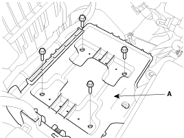
Remove the battery tray(A) while recovering refrigerant.
Remove the upper radiator hose(A) and lower radiator hose(B).
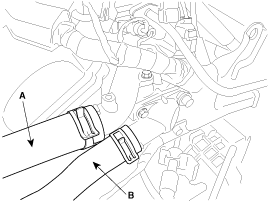
Remove the transaxle oil cooler hoses(A/T vehicles only).
Remove the fuel inlet hose(A) from the delivery pipe.
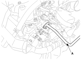
Disconnect the engine wiring harness connectors.
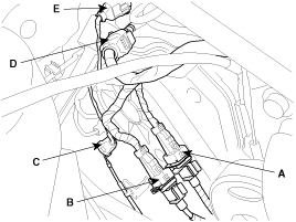
Disconnect the No.1/No.2 knock sensor connectors(A,B), the oil pressure switch connector(C), the ignition coil harness(D) and the No.1 VIS(Variable Induction System) connector(E).
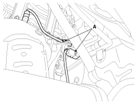
Disconnect the bank 1 front/rear O2 sensor connectors(A).
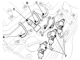
Disconnect the injection connectors(A,B,C), the ground lines(D), the condensor connector(E) and the Ignition coil connectors(F).
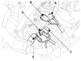
Disconnect the injection harness connector(A), the No.2 VIS(Variable Induction System) connector(B), the No.1/No.2 OCV(Oil Control Valve) connectors(C,D) and the OTS(Oil Temperature Sensor) connector(E).
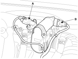
Disconnect the MAPS(Manifold Absolute Pressure Sensor) connector(A), the ETC(Electronic Throttle Control) connector(B) and the PCSV(Purge Control Solenoid Valve) connector(C).
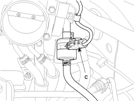
Disconnect the generator connector(A) and the air conditioning compressor connector(B).
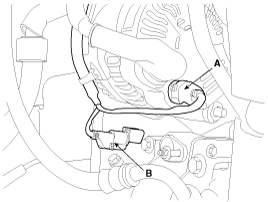
Disconnect the bank 2 CMP sensor connector(A) and the WTS(Water Temperature Sensor) connector(B).
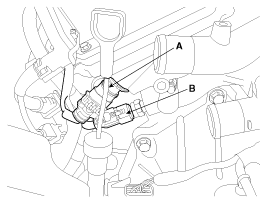
Disconnect the bank 2 front/rear O2 sensor connectors(A,B) and the CKP sensor connector(C).
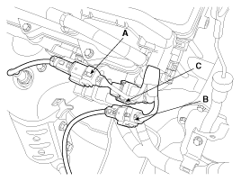
Disconnect the bank 1 CMP sensor connector(A).
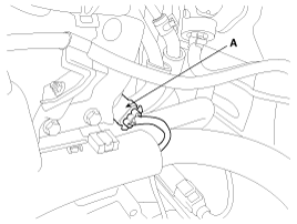
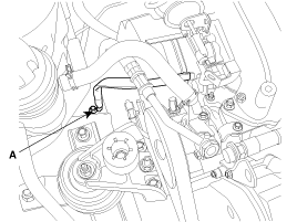
Disconnect ground lines(A) from the engine and the transaxle assembly.
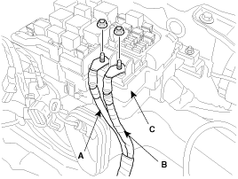
Disconnect the battery wirings(A,B) from the engine room fuse & relay box(C).
Remove the heater hoses.
Disconnect the brake vaccume hose(A).
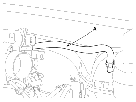
Disconnect the transaxle wiring harness connectors.(Refer to AT group).
After draining or gathering power steering fluid, disconnect the power steering hose(A).
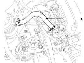
Remove the steering column shaft joint bolt.(Refer to ST group).
Disconnect the air conditioning compressor hoses.(Refer to HA group).
Remove the front wheels and tires.(Refer to DS group).
Lifting the vehicle, remove the under cover.
Drain the engine coolant, engine oil and transaxle fluid. Remove the radiator cap to speed coolant draining.
Remove the brake caliper.(Refer to DS group).
Disconnect the ABS connectors.(Refer to BR group).
Disconnect the stabilizer bar link from the struts.(Refer to SS group).
Remove the knockles from the struts.(Refer to DS group).
Remove the front muffler(A).
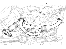
Disconnect the power steering return hose.
Remove the engine mounting bracket(A).
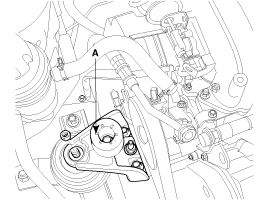
Remove the ECM(Electronic Controlled Mounting) nuts and the solenoid valve connector for A/T vehicles.
Remove the transaxle mounting bracket(A).
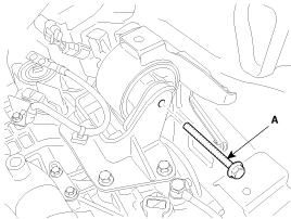
Supporting the engine and transaxle assembly with a jack, remove the assembly from the vehicle by loosening the subframe mouting bolts and lifting up the vehicle slowly.
When removing the engine and transaxle assembly, be careful not to damage any surrounding parts or body components.
Installation is in the reverse order of removal.
Perform the following :
Adjust the shift cable.
Refill the engine with engine oil.
Refill the transaxle with fluid.
Refill the radiator with engine coolant.
Bleed air from the cooling system with the heater valve open.
Clean the battery posts and cable terminals with sandpaper assemble them, then apply grease to prevent corrosion.
Inspect for fuel leakage.
After assembling the fuel line, turn on the ignition switch (do not operate the starter) so that the fuel pump runs for approximately two seconds and fuel line pressurizes.
Repeat this operation two or three times, then check for fuel leakage at any point in the fuel lines.