2.
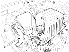
Remove the intake air hose and air cleaner assembly.
(1)
Disconnect the MAF connector(A).
(2)
Disconnect the breather hose(B) from air cleaner hose.
(3)
Remove the intake air hose and air cleaner assembly(C).
(4)
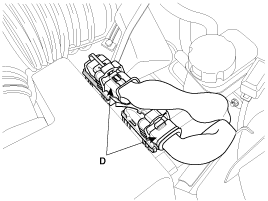
Disconnect the PCM connectors(D).
Remove the engine cover.
Remove the intake air hose and air cleaner assembly.
Disconnect the MAF connector(A).
Disconnect the breather hose(B) from air cleaner hose.
Remove the intake air hose and air cleaner assembly(C).
Disconnect the PCM connectors(D).
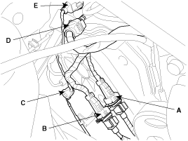
Disconnect the engine wiring harness connectors.
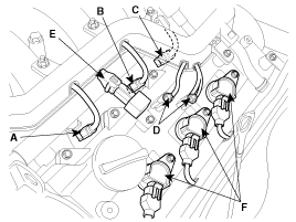
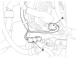
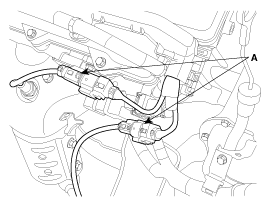
Disconnect the No.1/No.2 knock sensor connectors(A,B), the oil pressure switch connector(C), the ignition coil harness(D) and the No.1 VIS(Variable Induction System) connector(E).
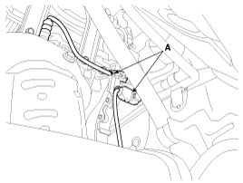
Disconnect the bank 1 front/rear O2 sensor connectors(A).
Disconnect the injection connectors(A,B,C), the ground lines(D), the condensor connector(E) and the Ignition coil connectors(F).
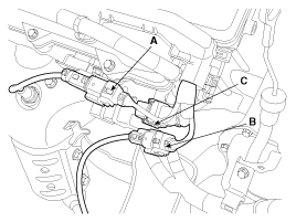
Disconnect the injection harness connector(A), the No.2 VIS(Variable Induction System) connector(B), the No.1/No.2 OCV(Oil Control Valve) connectors(C,D) and the OTS(Oil Temperature Sensor) connector(E).
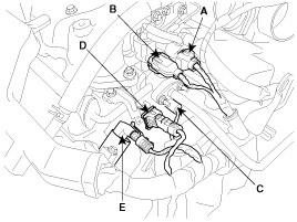
Disconnect the MAPS(Manifold Absolute Pressure Sensor) connector(A), the ETC(Electronic Throttle Control) connector(B) and the PCSV(Purge Control Solenoid Valve) connector(C).
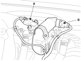
Disconnect the generator connector(A) and the air conditioning compressor connector(B).
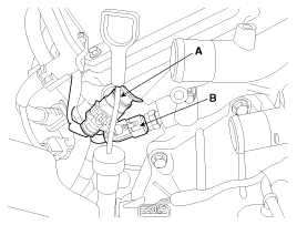
Disconnect the bank 2 CMP sensor connector(A) and the ECT(Engine Coolant Temperature) sensor connector(B).
Disconnect the bank 2 front/rear O2 sensor connectors(A,B) and the CKP sensor connector(C).
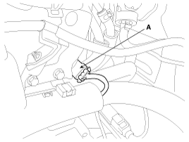
Disconnect the bank 1 CMP sensor connector(A).
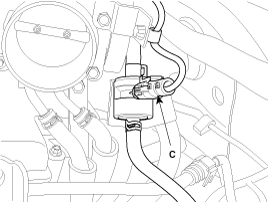
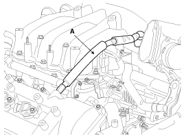
Remove the PCV(Pulge Control Valve) hose(A).
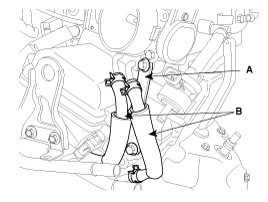
Remove the ETC(Electric Throttle Control) bracket(A) and the cooling hoses(B).
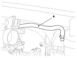
Disconnect the brake vaccume hose(A).
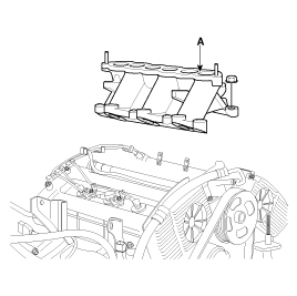
Remove the surge tank mounting bracket(A).
Remove the surge tank(A).
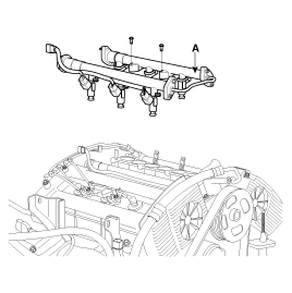
Remove the delivery pipe assembly(A).
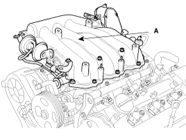
Remove the intake manifold assembly(A).
Remove the under cover.
Remove the front muffler(A).
Disconnect the oxygen sensor connectors(A).
Remove the oil level gauge.
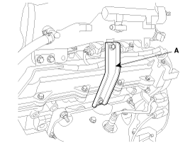
Remove the heat protector(A).
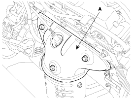
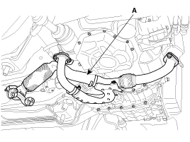
Remove the exhaust manifold assembly(A).
Install the intake manifold assembly with a new gasket to a cylinder head assembly. Tighten the bolts in two steps.
Tightening torque
Step 1(a~h): 3.9~5.9Nm(0.4~0.6kgf.m, 2.9~4.3lb-ft)
Step 2(1~8): 18.6~23.5Nm(1.9~2.4kgf.m, 13.7~17.4lb-ft)
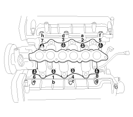
When installing the gasket on the cylinder head, check the indentification marks(LH/RH) not to be installed wrong.
Install the delivery pipe.
Connect the LH injector connector.
Install the surge tank.
Tightening torque
18.6~23.5Nm(1.9~2.4kgf.m, 13.7~17.4lb-ft)
Install the surge tank mounting bracket.
Tightening torque
18.6~23.5Nm(1.9~2.4kgf.m, 13.7~17.4lb-ft)
Install the ETC(Electronic Throttle Control) system fixing bracket.
Connect the hoses and connectors.
Install the air cleaner assembly.
Install the engine cover.
Install the exhaust manifold assembly with a new gasket.
Tightening torque
29.4~34.3Nm(3.0~3.5kgf.m, 21.7~25.3lb-ft)
Install the heat protector.
Tightening torque
16.7~21.6Nm(1.7~2.2kgf.m, 12.3~15.9lb-ft)
Install the front muffler assembly.
Tightening torque
39.2~58.8Nm(4.0~6.0kgf.m, 28.9~43.4lb-ft)
Connect the oxygen sensor connector.
Install the under cover.
