
The electronic control system used in the new generation auto transaxle is far superior to the previous systems. This system is able to adopt a variable shift pattern for smooth and problem free shifting.
A solenoid valve is applied to each of the clutches and brakes and is independently controlled. Feedback control and correction control is performed in all gears as well as utilization of mutual control system to increase shift feeling.
The torque converter damper clutch uses a partial lock up and full lock-up system. An additional control method called the HIVEC system (neural network) is adopted to increase shift feeling.
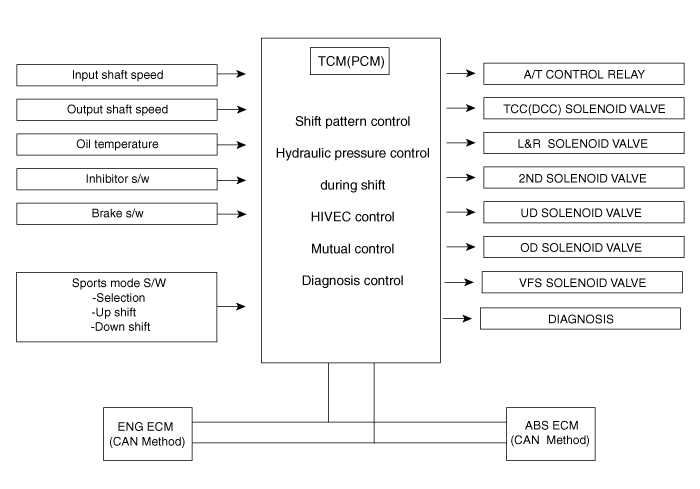
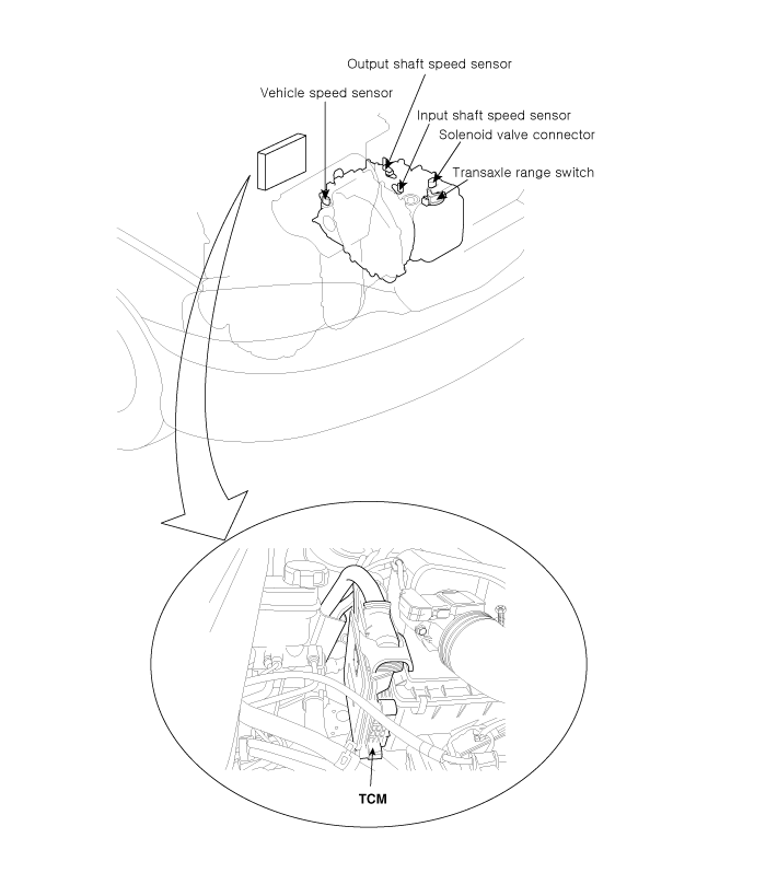
The TCM(PCM) is located on the intake manifold in the engine room.
Sensor | Function |
Input shaft speed sensor | Detect turbine speed at UD retainer |
Output shaft speed sensor | Detect T/F drive gear speed at T/F driven gear (4A/T) |
Crank angle sensor | Detect engine speed |
TPS(Gasoline) | Throttle opening ratio by potentiometer |
Air conditioner switch | A/C load by thermister |
Inhibitor switch | Select lever position by contact switch |
Brake switch | Brake pedal position |
Vehicle speed sensor | Detect vehicle speed by speedometer driven gear |
Sport mode switch | Sport mode On/Off signal |
Sport mode up-shift switch | Sport mode up-shift signal |
Sport mode downshift switch | Sport mode downshift signal |
Request of torque reduction | Send the request of torque reduction to ECM |
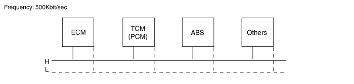
ABS-ECM, Engine ECM | In case of CAN communication |
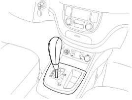
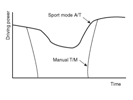
Sports mode allows the manual up-shift and downshift with the accelerator pedal is depressed. The prompt response and shift would be obtained due to the continuous shifting without cutting of driving power. The shifting time is also decreased about 0.1sec during up-shift, 0.2sec during downshift. As the selector lever is pushed upward or downward one time, the gear is up shifted or downshifted by one gear.
Items | Mode S/W | UP S/W | DOWN S/W |
D range selection | OFF | OFF | OFF |
Sports mode selection | ON | OFF | OFF |
Sports mode up-shift selection | ON | ON | OFF |
Sports mode downshift selection | ON | OFF | ON |
Previously, for different computers in the vehicle to share the same information, each signal required a different pin and wiring. However, with the introduction of a CAN system, only two lines are required to achieve the same function. The information is in digital format. This method does not use an integrated ECM.
Input signals to TCM(PCM) through ‘CAN communication’
- Engine rpm, TPS signal
- A/CON signal, Engine coolant temperature
- Quantity of intake airflow, Vehicle speed
- Shift holding signal (FTCS ON)
Output signals from TCM(PCM) through ‘CAN communication’
- Request signal for torque reduction
- ATF temperature, TCM(PCM) type, TCM(PCM) error or not
- Damper clutch ON, OFF / Gear position
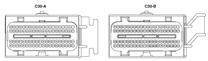
PIN No. | Check item | Condition | Input/Output value | Measurement Value | Remarks | |
Type | Level | |||||
A01 | 2nd CAN_HI | - | - | - | - | - |
A02 | 2nd CAN_LO | - | - | - | - | - |
A03 | P Range Selection | P Position Otherwise | DC Voltage | V_BAT Max. 1.0V | 12.9V 0V | |
A04 | R Range Selection | R Position Otherwise | DC Voltage | V_BAT Max. 1.0V | 12.3V 0V | |
A05 | N Range Selection | N Position Otherwise | DC Voltage | V_BAT Max. 1.0V | 13.2V 0V | |
A06 | D Range Selection | D Position Otherwise | DC Voltage | V_BAT Max. 1.0V | 13.2V 0V | |
A07 | Select Position | - | DC Voltage | V_BAT Max. 1.0V | 13.2V 0V | |
A08 | Up Position | - | DC Voltage | V_BAT Max. 1.0V | 13.2V 0V | |
A09 | Down Position | - | DC Voltage | V_BAT Max. 1.0V | 13.2V 0V | |
A12 | N.A | - | - | - | - | |
A14 | N.A | - | - | - | - | |
A19 | N.A | - | - | - | - | |
A20 | A/T Control Relay | Relay On Relay Off | DC Voltage | V_BAT Max. 1.0V Vpeak : Max. 70V Resistance : 680Ω | 13.8V 0V -0.7V Resistance : 680Ω | |
W/H Open | DTC Spec : P0890 | DTC : P0890 | ||||
A27 | Diagnosis "K" | Communicated with GST | Pulse | At transmitting HI : V_BAT* 80%↑ LO : V_BAT*20%↓ AT receiving HI : V_BAT* 70%↑ LO : V_BAT*30%↓ | 11.3V 0.14/ 0.32V | V_BAT : 13.2V |
A31 | N.A | - | - | - | - | |
A32 | A/C Pressure Analog | - | - | - | - | - |
A34 | N.A | - | - | - | - | |
A36 | N.A | - | - | - | - | |
A37 | N.A | - | - | - | - | |
A41 | CAN_HI | Recessive Dominant | Pulse | 2.0 ~ 3.0 V 2.75 ~ 4.5 V | 3.85V 2.5V | |
A42 | CAN_LO | Recessive Dominant | Pulse | 2.0 ~ 3.0 V 0.5 ~ 2.25 V | 2.55V 1.34V | |
A60 | A/T PWR Source | IG Off IG On IG. Key On IG. Key Off Idle Key Off from Idle Fuse 1/2/3 Removal Condition | DC Voltage | Max. 0.5 V V_BAT MAX. +/- 75V (ECU GND) MAX. +/- 75V (ECU GND) MAX. +/- 75V (ECU GND) MAX. +/- 75V (ECU GND) MAX. +/- 75V (ECU GND) | 0V 11.9V +30V / -10V or less ↑ | |
W/H Open | DTC Spec : P0888 | DTC : P0888 | ||||
A73 | Shift Position Signal(To Cluster) | Running 1 gear 2 gear 3 gear 4 gear 5 gear | Pulse Duty ↑ ↑ ↑ ↑ | HI : V_BAT LO : Max. 1.0V Freq.: 50±2Hz (Reference) 12.5±2% 27.5±2% 42.5±2% 57.5±2% 72.5±2% | N.A | Sports mode |
B03 | UD Solenoid | Shifting | Pulse | HI : V_BAT LO : Max. 1.0V Vpeak : Max. 70V | 14.4V 0.35V 56.3V | |
W/H Open | DTC Spec : P0755 | DTC : P0755 | ||||
B05 | N.A | - | - | - | - | |
B06 | Oil temperature sensor_ATM | Idle | Analog | 0.5V ~ 4.5V | 4.4V 3.1V | 16Hz |
B09 | Output speed sensor | 30kph | Pulse | HI : Min. 4.0V LO : Max. 1.0V | 5.08V 0.34V | |
W/H Open | DTC Spec : P0722 | DTC : P0722 | ||||
B10 | Input speed sensor | Idle | Pulse | HI : Min. 4.0V LO : Max. 1.0V | 5.06V 0.35V | 630Hz |
W/H Open | DTC Spec : P0717 | DTC : P0717 | ||||
B20 | N.A | - | - | - | - | |
B22 | LR Solenoid | Shifting | Pulse | HI : V_BAT LO : Max. 1.0V Vpeak : Max. 70V | 13.9V 0.38V 56.1V | |
W/H Open | DTC Spec : P0750 | DTC : P0750 | ||||
B26 | N.A | - | - | - | - | |
B27 | N.A | - | - | - | - | |
B33 | GND_Sensor | Idle | DC Voltage | Max. 50 mV | 13mV | WTS & OTS_ATM |
W/H Open | DTC Spec : P0118/ 1115 | DTC : P0118/ P1115 | ||||
B42 | OD Solenoid | Shifting | Pulse | HI : V_BAT LO : Max. 1.0V Vpeak : Max. 70V | 15.4V 0.45V 56.3V | |
W/H Open | DTC Spec : P0765 | DTC : P0765 | ||||
B43 | DCC solenoid | Lock_Up on | Pulse | HI : V_BAT LO : Max. 1.0V Vpeak : Max. 70V | 15.4V 0.45V 56.3V | |
W/H Open | DTC Spec : P0743 | DTC : P0743 | ||||
B44 | RED Solenoid | Shifting | Pulse | HI : V_BAT LO : Max. 1.0V Vpeak : Max. 70V | 15.4V 0.45V 56.3V | |
W/H Open | DTC Spec : P0770 | DTC : P0770 | ||||
B45 | 2ND Solenoid | Shifting | Pulse | HI : V_BAT LO : Max. 1.0V Vpeak : Max. 70V | 15.4V 0.45V 56.3V | |
W/H Open | DTC Spec : P0760 | DTC : P0760 | ||||
B46 | N.A | - | - | - | - | |
B47 | N.A | - | - | - | - | |
B59 | Variable Solenoid (-) | Idle | Pulse | HI : V_BAT LO : Max. 1.0V Vpeak : Max. 70V | 1.8/1.2V - N range 0.03V(DC) - D range | 600Hz |
W/H Open | DTC Spec : P0748 | DTC : P0748 | ||||
B65 | N.A | - | - | - | - | |
B66 | N.A | - | - | - | - | |
B75 | Variable Solenoid (+) | Idle | Pulse | HI : V_BAT LO : Max. 1.0V Vpeak : Max. 70V | 13.1V -0.07V | |
W/H Open | DTC Spec : P0748 | DTC : P0748 | ||||
B80 | N.A | - | - | - | - | |