2.
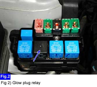
Remove the glow relay from the fusible link box.
First of all check damage of harness and terminals : Check terminals for contact resistance, corrosion and deformation.
IG KEY "OFF", ENGINE "OFF"
Remove the glow relay from the fusible link box.
Measure the voltage of the glow relay terminal. (Fusible link box side)
Case 1 : In case that battery voltage is not supplied at terminal "1".
Repair Glow fusible link (80A) blown on the fusible link box.
If fusible link is blown again,
- Repair short to ground in power circuit between fusible link box connector (C218) terminal "5" and glow plug connector (C206) terminal "1".
- Measure the resistance of the glow plug.
Case 2 : In case that battery voltage is not supplied at terminal "4".
Repair "sensor#2 fuse (15A) blown on the U/H junction box.
Inspect normal operation and DTC of Boost pressure actuator, Throttle flap actuator, EGR actuator and CMPS.(Sensor#2 fuse supply battery power to Boost pressure actuator, Throttle flap actuator, EGR actuator and CMPS)
If sensor#2 fuse (15A) is blown again,
- Repair short to ground in power circuit of glow relay, Boost pressure actuator, Throttle flap actuator, EGR actuator and CMPS.
Case 3 : In case that 3.5 V is not supplied on the terminal "2" at IG KEY "ON".
Repair open between glow relay connector (C218) terminal "2" and ECM connector (C230-K) terminal "93".
DTC "P0670 Glow relay circuit malfunction" would be displayed in this case.
IG KEY "OFF", ENGINE "OFF"
Remove the glow relay from the fusible link box.
Before measuring resistance, you must calibrate(0Ω) the tester.
Measure the resistance between glow relay terminal "5" and chassis ground.
"Multitester Calibration" of "Details Inspection(Equipment Setting)" reference
Specification : Below 1.0 Ω ( 20℃ ) (resistance can be changed by glow plug temperature)
Case 1 : In case that the resistance between glow relay terminal "5" and chassis ground is normal.
Go to "Glow plug relay inspection" procedure.
Case 2 : In case that there is no continuity between glow relay connector (C218) terminal "5" and chassis ground.
Repair open or poor connection between glow relay connector (C218) terminal "5" and glow plug connector (C206) terminal "1".
Repair open or poor connection between glow plug connector (C206) terminal "1" and glow plugs.
If glow plug circuit is normal, glow plugs (4EA) are open.
- Go to "Glow plug inspection" procedure.
Case 3 : In case that there is high resistance between terminal "5" and chassis ground.
Go to "Glow plug current inspection" or "Glow plug inspection" procedure.
