Has a problem been found?
YES
Repair as necessary and go to "Verification of Vehicle Repair" procedure.
NO
Go to " Signal Circuit Inspection " procedure.
Many malfunctions in the electrical system are caused by poor harness and terminals. Faults can also be caused by interference from other electrical systems, and mechanical or chemical damage.
Thoroughly check connectors for looseness, poor connection, bending, corrosion, contamination, deterioration, or damage.
Has a problem been found?
YES
Repair as necessary and go to "Verification of Vehicle Repair" procedure.
NO
Go to " Power Ciurcuit Inspection" procedure.
This procedure is applied to vehicle with ABS (or ESP). In case of no ABS(or ESP), refer to "C1203 Wheel speed sensor front-RH open/short".
Check short to ground in harness
IG "OFF"
Disconnect PCM connector and ABS or EPS control module connector.
Measure resistance between terminal 52 of PCM harness connector and chassis ground.
Specification : Infinite
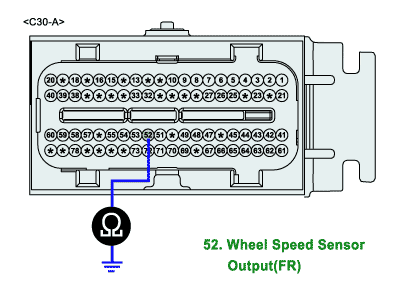
Is the measured resistance within specifications?
YES
▶ Go to "Check open in harness" as follows.
NO
▶ Repair short to ground in harness, and go to "Verification of Vehicle Repair" procedure.
Check for open in harness
Ignition "OFF"
Disconnect PCM connector and ABS or ESP control module connector.
Measure resistance between terminal "52" of PCM harness connector and terminal "13(With ESP: terminal 6)" of ABS control module harness connector.
Specification : Approx. below 1Ω
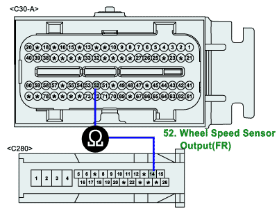
This picture is only applied to vehicle with ABS
Is the measured resistance within specifications?
YES
▶ Go to " Check wheel speed sensor " procedure.
NO
▶ Check open in harenss.
▶ Repair or replace as necessary and then, go to " Verification of Vehicle Repair" procedure.
Check wheel speed sensor
IG "OFF"
Check open or short in wheel speed sensor (Refer to "C1203 Wheel speed sensor front-RH open/short")
Is the wheel speed sensor normal?
YES
▶ Substitute with a known - good PCM/ ABS or ESP control unit and check for proper operation. If the problem is corrected, replace PCM/ ABS or ESP control unit and go to "Verification of Vehicle Repair" procedure.
NO
▶ Repair or replace it as necessary.
▶ And then go to " Verification of Vehicle Repair" procedure.
There is a memory reset function on scantool that can erase optional parts automatically detected and memorized by PCM. After testing PCM on the vehicle, use this function to reuse the PCM on the others
Check voltage from sensor side
IG "OFF"
Disconnect vehicle speed sensor connector.
IG "ON" and ENG "OFF"
Measure voltage between terminal 3 of vehicle speed sensor harness connector and chassis ground.
Specification : Approx. 8~11.5
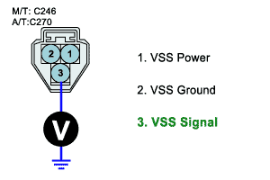
Is the measured voltage within specifications?
YES
Go to "Check voltage from PCM side" as follows.
NO
Repair open or short to ground in harness, and go to "Verification of Vehicle Repair" procedure.
Check voltage from PCM side
IG "OFF"
Disconnect PCM connector and vehicle speed sensor connector.
IG "ON" and ENG "OFF"
Measure voltage between terminal "52" of PCM harness connector and chassis ground.
Specification : Approx. 8~11.5V
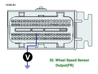
Is the measured voltage within specifications?
YES
Go to "Ground circuit inspection" procedure.
NO
Check open in harness.
Repair or replace as necessary and then, go to "Verification of Vehicle Repair" procedure.
Check Voltage
IG "OFF"
Disconnect vehicle speed sensor connector.
IG "ON" and ENG "OFF"
Measure voltage between terminal 1 of vehicle speed sensor harness connector and chassis ground.
Specification : Approx. 11.5~13V
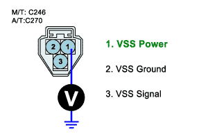
Is the measured voltage within specifications?
YES
Go to "Signal circuit inspection" procedure.
NO
Repair open or short to ground in harness, and go to "Verification of Vehicle Repair" procedure.
Especially Check the fuse related to Power for blown-off.
IG "OFF"
Disconnect vehicle speed sensor connector.
IG "ON" and ENG "OFF"
Measure voltage between terminal 1 of vehicle speed sensor harness connector and chassis ground.(Fig.A)
Measure voltage between terminals 1 and 2 of vehicle speed sensor harness connector.(Fig.B)
Specification : Measurement "A" - Measurement "B" = Approx. below 200mV
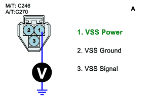
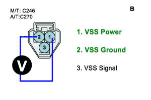
Is the measured voltage within specifications?
YES
Substitute with a known - good vehicle speed sensor and check for proper operation. if the problem is not corrected, substitute with a known - good PCM and check for proper operation. And go to "Verification of Vehicle Repair" procedure.
NO
Repair open or contact resistance in harness, and go to "Verification of Vehicle Repair" procedure.
There is a memory reset function on scantool that can erase optional parts automatically detected and memorized by PCM. After testing PCM on the vehicle, use this function to reuse the PCM on the others.