
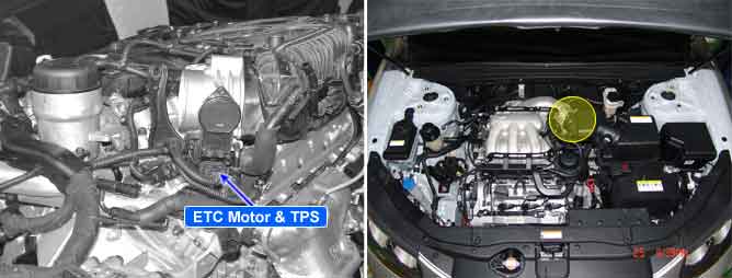
The Electronic Throttle Control(ETC) system is made of the components throttle body, Throttle Position Sensor(TPS)1&2 and Accelerator Position Sensor(APS) 1&2. TPS1&2 are sharing the same source voltage and ground.The throttle valve opening is control by throttle motor which is controlled by PCM. The opposite position indicator shows inverted signal characteristics.TPS1 output voltage increases smoothly in proportion with the throttle valve opening angle after starting. TPS2 output voltage decreases in inverse proportion with the throttle valve opening angle after starting. TPS provides feedback to the PCM to control the throttle motor in order to control the throttle valve opening angle properly in response to the driving condition.
Checking output signals from TPS2 every 8.5 sec. under detecting condition, if an output signal is below 0.25V for more than 0.1 sec., PCM sets P0222.
Item | Detecting Condition | Possible Cause |
DTC Strategy | ● Signal low | ● Poor connection ● Open or short to ground in power harness ● Open or short to ground in signal harness ● TPS ● PCM |
Enable condition | ● IG "ON" | |
threshold value | ● The signal voltage of TPS < 0.25V | |
diagnosis time | ● Continuous (More than 0.1 sec. failure for every 8.5 sec.test) | |
MIL ON condition | ● 1 driving cycle |
Throttle opening ( ° ) | Output voltage(V) [Vref=5.0] | Throttle opening ( ° ) | Output voltage(V) [Vref=5.0] | ||
TPS1 | TPS2 | TPS1 | TPS2 | ||
0° | 0.0V | 5.0V | 60° | 2.7V | 2.3V |
10° | 0.5V | 4.5V | 70° | 3.2V | 1.8V |
20° | 0.9V | 4.1V | 80° | 3.6V | 1.4V |
30° | 1.4V | 3.6V | 90° | 4.1V | 0.9V |
40° | 1.8V | 3.2V | 100° | 4.5V | 0.5V |
50° | 2.3V | 2.7V | 110° | 5.0V | 0.0V |
Fig 1) No acceleration under IG ON condition
Fig 2) WOT under IG ON condition