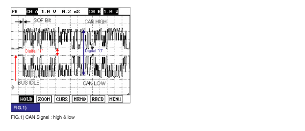
Shift to N Range.
Specification : Signal Waveform & Data

The above value is only for reference.
The actual value may differ from it according to various engine condition.

TPS(or APS) signal which is used for judging driver's intention is received from engine ECU through CAN line.
This signal is a criteria signal to determind amount of torque distribution at front/rear wheel with steering angle sensor, wheel speed sensor, break signal.

This code related to communication line between ECU and TCCU is set when CAN signal from ECU can't received for more than 1sec or ECU internal error occur.
If failure is detected TCCU prohibits the ITM control and cuts the current to control coil.
Item | Detecting Condition | Possible Cause |
DTC Strategy | ● Loss of signal out of range | ● ECM,TCCU connector looseness and poor terminal to wire connection ● CAN HIGH/LOW circuit open/short ● APS(TPS) faulty ● Faulty ECM ● Faulty TCCU |
Enable Conditions | ● Message present 1.0 sec self clearing | |
Threshold Value | ● A fault code of FFH from the C.A.N. Bus, Signal lost for 1 sec. Fault code stored in memory | |
Diagnosticn Time | ● 1 sec | |
MIL on condition | ● 0.5 Sec | |
Fail Safe | ● TPS=0 ITM Controller will not re-act to pre-empt. Pre-empt=0. The ECU will not send current to the clutch coil |

Ignition ON, Engine : ON.
TCCU connector : Connect.
Monitor signal waveform between terminal 4, 5 of TCCU harness connector and chassis ground.
Shift to N Range.
Specification : Signal Waveform & Data

The above value is only for reference.
The actual value may differ from it according to various engine condition.
Is CAN Signal display near the specified value?

▶ Fault is intermittent caused by poor contact in the sensor's and/or TCCU's connector or was repaired and TCCU memory was not cleared.Thoroughly check connectors for looseness, poor connection, bending, corrosion, contamination, deterioration, or damage. Repair or replace as necessary and then go to "Verification of Vehicle Repair" procedure.

▶ Go to " CAN comm. Line Inspection " procedure.
Many malfunctions in the electrical system are caused by poor harness and terminals. Faults can also be caused by interference from other electrical systems, and mechanical or chemical damage.
Thoroughly check connectors for looseness, poor connection, bending, corrosion, contamination, deterioration,or damage.
Has a problem been found?

▶ Repair as necessary and go to "Verification of Vehicle Repair" procedure.

▶ Go to " CAN Signal Inspection " procedure.
IG "OFF" & ENG "OFF"
TCCU connector : Disconnect.
Measure resistance between terminal "4" of the TCCU harness connector and terminal "5" of the TCCU harness connector.
Specification : Approx. 60Ω

The above value is only for reference.
The actual value may differ from it according to various engine condition.
Is resistance display near the specified value?

▶ Fault is intermittent caused by open or short in CAN signal harnessor was repaired and TCCU memory was not cleared. Go to the applicable troubleshooting procedure.

▶ Check for open/short in CAN comunication line of TCCU circuit.
▶ Check for the signal or component of Engine control module.
▶ Repair as necessary and then go to "Verification of Vehicle Repair" procedure.
Connect scan tool and select "Diagnostic Trouble Codes(DTCs)" mode.
Using scantool, Clear DTC.
Operate the vehicle within DTC Enable conditions in General information.
Are any DTCs present ?

▶ Go to the applicable troubleshooting procedure.

▶ System is performing to specification at this time.