Disconnect the stop lamp switch (A) connector and loosen the stop lamp switch lock nut.
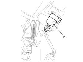
Disconnect the stop lamp switch (A) connector and loosen the stop lamp switch lock nut.

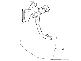
Adjust the brake pedal height (A) as illustration below.
Pedal height: 214 mm (8.43 in)
Adjust the stop lamp switch clearance and brake pedal free play.
Stop lamp clearance: 1 ~ 2 mm (0.04 ~ 0.08 in)
Pedal free play: 3.0 ~ 8.0 mm (0.12 ~ 0.31)
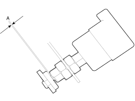
Adjust the brake pedal free play using the stop lamp switch lock nut.
Remove the lower crash pad.
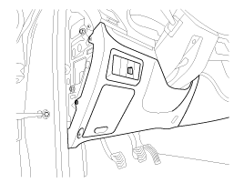
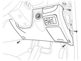
Disconnect the stop lamp switch (A) connector.

Remove the snap pin (A) and joint pin (B).
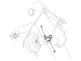
Remove the brake pedal by loosen the joint bolt and nut.
Tightening torque Nm (kgf.m, lb-ft):
24.5 ~ 34.3 (2.5 ~ 3.5, 18.1 ~ 25.3)
Remove the lower crash pad.

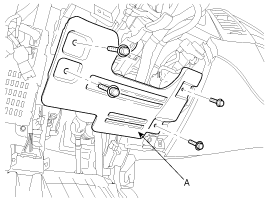
Remove the reinforcing panel (A).
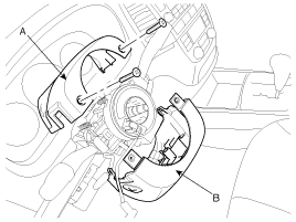
Loosen the screws, and then remove the steering column upper (A) and lower shrouds (B).
Disconnect the connectors (A) from the steering column shaft assembly.
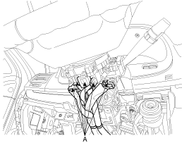
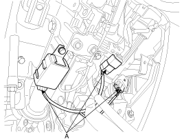
Disconnect the ignition switch connector (A) and then remove the steering column assembly by loosening the steering column mounting bolts and nuts.
Tightening torque Nm (kgf.m, lb-ft):
13 ~ 18 (1.3 ~ 1.8, 9.4 ~ 13.0)
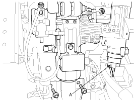
Remove the universal joint bolt and then remove the steering column shaft assembly.
Remove the relay box(A) with mounting nut(B).
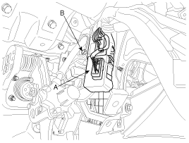
Remove the snap pin(A) and joint pin(B).

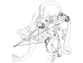
Disconnect the connectors (A) from the adjustable brake pedal assembly.
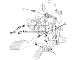
Remove the mounting nuts (9ea) of the adjustable brake pedal assembly.
Tightening torque Nm (kgf.m, lb-ft):
Nuts(A) : 16.7 ~ 25.5 (1.7 ~ 2.6, 12.3 ~ 18.8)
Nuts(B) : 12.7 ~ 15.7 (1.3 ~ 1.6, 9.4 ~ 11.6)
Nuts(C) : 7.8 ~ 9.8 (0.8 ~ 1.0, 5.8 ~ 7.2)
Remove the adjustable brake pedal assembly.
Installation is the reverse of removal.
Before installing the pin, apply the grease to the joint pin.
Use a new snap pin whenever installing.
Check the brake pedal operation.