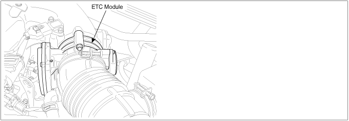
The Electronic Throttle Control(ETC) system is made of the components throttle body, Throttle Position Sensor(TPS)1&2 and Accelerator Position Sensor(APS) 1&2. The throttle body contains the actuator, the throttle plate and the throttle position sensor (potentiometer), which are integrated in one housing. The actuator consists of a DC motor with a two-stage gear. The opening angle of the throttle valve is detected by the throttle position sensor which is mounted on the throttle body. And it provides feedback to the PCM to control the throttle motor in order to control the throttle valve opening angle properly in response to the driving condition.
DTC DESCRIPTION
Checking output signals from TPS under detecting condition, if the difference between real and target throttle position is above the specified value, PCM sets P0638 and then MIL(Malfunction Indication Lamp) turns on.
DTC DETECTING CONDITION
Item
Detecting Condition
Possible cause
DTC Strategy
●
Monitor the throttle position
●
Throttle stuck
●
Open in motor circuit
●
Faulty motor
●
Faulty PCM
Enable Conditions
●
Engine running
●
Battery voltage 〉5V
Thresh
old
value
Case1
●
The difference between the real ETS motor & TPS value and the target ETS motor & TPS value is over 4.5°.
Case2
●
When real Throttle position is below 36°, (the real throttle position - the target throttle position) < - 4.5°
Case3
●
(the real throttle position - the target throttle position) < - 18°
Diagnosis Time
●
Continuous
MIL On Condition
●
1 driving cycle
※ If Main relay has a fault(ex. Open) while the engine is running, the DTCs,P0638/P0685/P1295/P2106, can happen at the same time.
<DTC Name>
-
P0638 Throttle Actuator Control Range/Performance(Bank 1)
-
P0685 PCM/PCM Power Relay Control Circuit /Open
-
P1295 Throttle Actuator Control System - Power Management
-
P2106 Throttle Actuator Control System - Forced Limited Power
SPECIFICATION
Throttle opening ( ° )
Output voltage (V) [Vref = 5.0V]
TPS1
TPS2
0°
0.0V
5.0V
10°
0.5V
4.5V
20°
0.9V
4.1V
30°
1.4V
3.6V
40°
1.8V
3.2V
50°
2.3V
2.7V
60°
2.7V
2.3V
70°
3.2V
1.8V
80°
3.6V
1.4V
90°
4.1V
0.9V
100°
4.5V
0.5V
110°
5.0V
0.0V
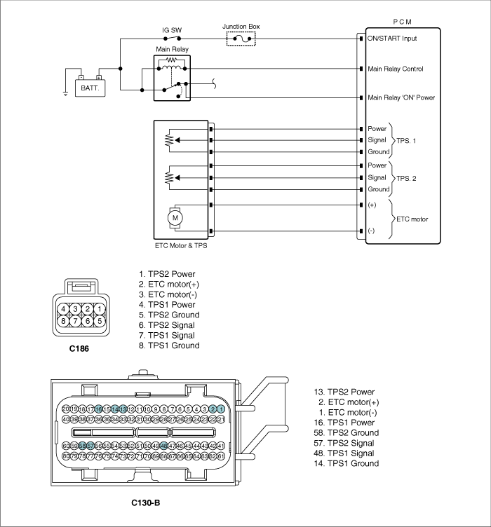
SCHEMATIC DIAGRAM
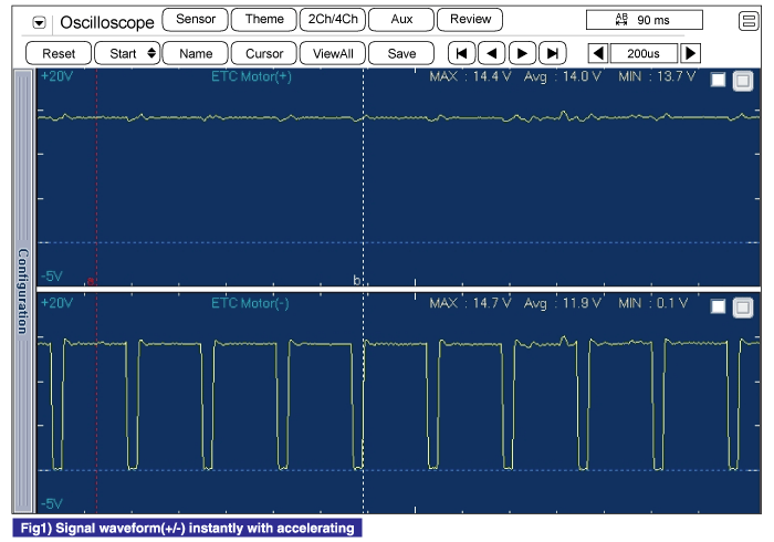
SIGNAL WAVEFORM AND DATA
MONITOR DTC STATUS
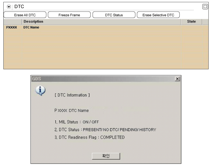
1.
Check DTC Status
(1)
Connect scantool to Data Link Connector(DLC).
(2)
IG "ON".
(3)
Select "DTC" button, and then Press "DTC Status" to check DTC's information from the DTCs menu.
(4)
Read "DTC Status" parameter.
(5)
Is parameter displayed "Present fault"?
▶ Go to "Terminal and connector inspection" procedure.
▶ Fault is intermittent caused by poor contact in the sensor's and/or PCM's connector or was repaired and PCM memory was not cleared. Thoroughly check connectors for looseness, poor connection, ending, corrosion, contamination, deterioration, or damage. Repair or replace as necessary and go to "Verification of Vehicle Repair" procedure.
TERMINAL AND CONNECTOR INSPECTION
1.
Many malfunctions in the electrical system are caused by poor harness and terminal condition. Faults can also be caused by interference from other electrical systems, and mechanical or chemical damage.
2.
Thoroughly check connectors for looseness, poor connection, bending, corrosion, contamination, deterioration, or damage.
3.
Has a problem been found?
▶ Repair as necessary and go to "Verification of Vehicle Repair" procedure
▶ Go to " Control Circuit Inspection " procedure.
CONTROL CIRCUIT INSPECTION
■ Check voltage
1.
IG "OFF"
2.
Disconnect ETC Motor & TPS connector.
3.
IG "ON" and ENG "OFF"
4.
Measure the voltage between ETC motor(+)/(-) of ETC Motor & TPS harness connector and chassis ground.
Specification : Approx. B+
5.
Is the measured voltage within specification?
▶ Go to "Component Inspection" procedure.
▶ Go to "Check open in harness" as follows.
■ Check open in harness
1.
IG "OFF"
2.
Disconnect ETC Motor & TPS connector and PCM connector.
3.
Measure the resistance between ETC motor (+) terminal of ETC Motor & TPS harness connector and ETC motor (+) terminal of PCM harness connector.
4.
Measure the resistance between ETC motor (-) terminal of ETC Motor & TPS harness connector and ETC motor (-) terminal of PCM harness connector.
Specification : Approx. below 1Ω
5.
Is the measured resistance within specification ?
▶ Go to "Component Inspection" procedure.
▶ Repair open in motor harness and go to "Verification of Vehicle Repair" procedure.
COMPONENT INSPECTION
■ Check throttle valve for stuck
1.
IG "OFF".
2.
Disconnect the air hose between throttle body and air mass flow sensor.
3.
Check stuck on throttle valve.
4.
Is the throttle valve normal?
▶ Go to "Check ETC motor resistance" as follows.
▶ Repair or replace as necessary and go to "Verification of Vehicle Repair" procedure.
■ Check ETC motor resistance
1.
IG "OFF".
2.
Disconnect ETC Motor & TPS connector.
3.
Measure the resistance between ETC motor(+) and (-) terminals of ETC Motor & TPS connector (component side).
▶ Substitute with a known - good ETC motor and check for proper operation. If the problem is corrected, replace ETC motor and go to "Verification of Vehicle Repair" procedure.
※ Procedure of ETS Initialization
1. Erase the trouble codes on PCM
Turn the ignition key off and keep this condition until the main relay is turned off.(It will takes 10 second)
3. Turn ignition key on more than 1second to record the throttle motor position on the EEPROM
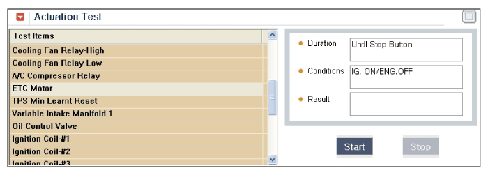
■ ETC motor actuation test
1.
IG "OFF".
2.
Connect ETC motor & TPS connector.
3.
After IG "ON", execute the "ETC motor actuation test" by Scantool.
4.
Does the "ETC motor actuation test" execute normally ?
▶ Substitute with a known - good PCM and check for proper operation. If the problem is corrected, replace PCM and go to "Verification of Vehicle Repair" procedure.
▶ Substitute with a known - good ETC motor and check for proper operation. If the problem is corrected, replace ETC motor and go to "Verification of Vehicle Repair" procedure.
※ Procedure of ETS Initialization
1. Erase the trouble codes on PCM
2. Turn the ignition key off and keep this condition until the main relay is turned off.(It will take 10 seconds)
3. Turn ignition key on more than 1second to record the throttle motor position on the EEPROM
VERIFICATION OF VEHICLE REPAIR
After a repair, it is essential to verify that the fault has been corrected.
1.
Connect scantool and select "DTC" button.
2.
Press "DTC Status" button and confirm that "DTC Readiness Flag" indicates "Completed". If not, drive the vehicle within conditions noted in the freeze frame data or enable conditions
3.
Read "DTC Status" parameter
4.
Is parameter displayed "History(Not Present) fault"?
▶ System performing to specification at this time. Clear the DTC