Stall speed too low in both "D" and "R" ranges
Malfunction of torque converter(D)
Insufficient engine output
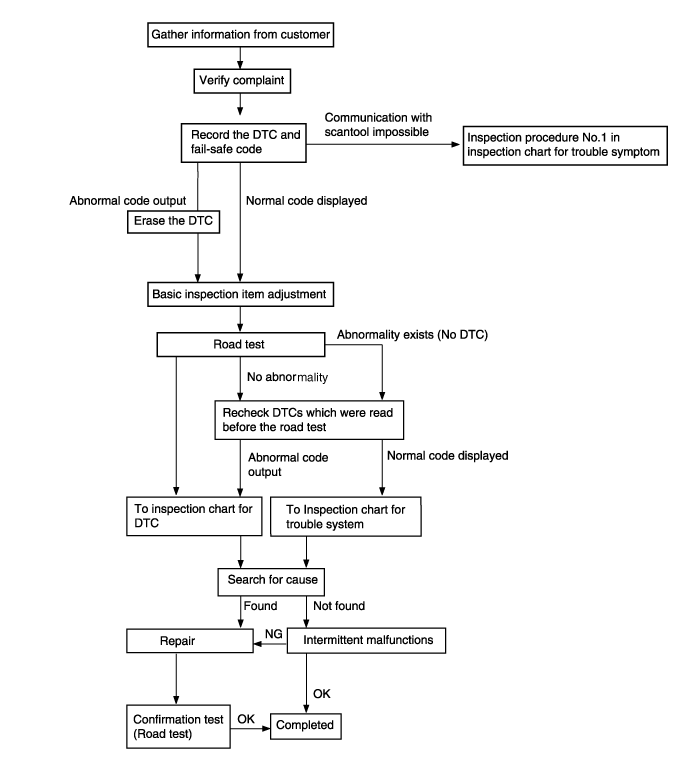
Trouble symptom | Probable cause | |
Communication with HI-SCAN is not possible If communication with the HI-SCAN is not possible, the cause is probably a defective diagnosis line or the TCM(PCM) is not functioning. | - Malfunction diagnosis line - Malfunction of connector - Malfunction of the TCM(PCM) | |
Driving impossible | Starting impossible Starting is not possible when the selector lever is in P or N range. In such cases, the cause is probably a defective engine system, torque converter or oil pump. | - Malfunction of the engine system - Malfunction of the torque converter - Malfunction of the oil pump |
Does not move forward If the vehicle does not move forward when the selector lever is shifted from N to D, 3, 2 or L range while the engine is idling, the cause is probably abnormal line pressure or a malfunction of the underdrive clutch or valve body. | - Abnormal line pressure - Malfunction of the underdrive solenoid valve - Malfunction of the underdrive clutch - Malfunction of the valve body | |
Does not reverse If the vehicle does not reverse when the selector lever is shifted from N to R range while the engine is idling, the cause is probably abnormal pressure in the reverse clutch or low and reverse brake or a malfunction of the reverse clutch, low and reverse brake or valve body. | - Abnormal reverse clutch pressure - Abnormal low and reverse brake pressure - Malfunction of the low and reverse brake solenoid valve - Malfunction of the reverse clutch - Malfunction of the low and reverse brake - Malfunction of the valve body | |
Does not move (forward or reverse) If the vehicle does not move forward or reverse when the selector lever is shifted to any position while the engine is idling, the cause is probably abnormal line pressure or a malfunction of the power train, oil pump or valve body. | - Abnormal line pressure - Malfunction of power train - Malfunction of the oil pump - Malfunction of the valve body | |
Malfunction when starting | Engine stalling when shifting If the engine stalls when the selector lever is shifted from N to D or R range while the engine is idling, the cause is probably a malfunction of the engine system, damper clutch solenoid valve, valve body or torque converter (damper clutch malfunction). | - Malfunction of the engine system - Malfunction of the damper clutch control solenoid valve - Malfunction of the valve body - Malfunction of the torque converter (Malfunction of the damper clutch) |
Shocks when changing from N to D and large time lag If abnormal shocks or a time lag of 2 seconds or more occur when the selector lever is shifted from N to D range while the engine is idling, the cause is probably abnormal underdrive clutch pressure or a malfunction of the underdrive clutch, valve body or idle position switch. | - Abnormal underdrive clutch pressure - Abnormal low and reverse brake pressure - Malfunction of the underdrive solenoid valve - Malfunction of the valve body - Malfunction of the idle position switch | |
Malfunction when starting | Shocks when changing from N to R and large time lag If abnormal shocks or a time lag of 2 seconds or more occur when the selector lever is shifted from N to R range while the engine is idling, the cause is probably abnormal reverse clutch pressure or low and reverse brake pressure, or a malfunction of the reverse clutch, low and reverse brake, valve body or idle position switch. | - Abnormal reverse clutch pressure - Abnormal low and reverse brake pressure - Malfunction of the low and reverse solenoid valve - Malfunction of the reverse clutch - Malfunction of the low and reverse brake - Malfunction of the valve body - Malfunction of the idle position switch |
Shocks when changing from N to D, N to R and large time lag If abnormal shocks or a time lag of 2 seconds or more occur when the selector lever is shifted from N to D range and from N to R range while the engine is idling, the cause is probably abnormal line pressure or a malfunction of the oil pump or valve body. | - Abnormal line pressure - Malfunction of the oil pump - Malfunction of the valve body | |
Malfunction when shifting | Shocks and running up If shocks occur when driving due to up shifting or down shifting and the transmission speed becomes higher than the engine speed, the cause is probably abnormal line pressure or a malfunction of a solenoid valve, oil pump, valve body or of a brake or clutch. | - Abnormal line pressure - Malfunction of each solenoid valve - Malfunction of the oil pump - Malfunction of the valve body - Malfunction of each brake or each clutch |
Displaced shifting points | All points If all shift points are displaced while driving, the cause is probably a malfunction of the output shaft speed sensor, TPS or of a solenoid valve. | - Malfunction of the output shaft speed sensor - Malfunction of the throttle position sensor - Malfunction of each solenoid valve - Abnormal line pressure - Malfunction of the valve body - Malfunction of the TCM(PCM) |
Some points If some of the shift points are displaced while driving, the cause is probably a malfunction of the valve body, or it is related to control and is not an abnormality. | - Malfunction of the valve body | |
Does not shift | No diagnosis codes If shifting does not occur while driving and no diagnosis codes are output, the cause is probably a malfunction of the transaxle range switch, or TCM(PCM) | - Malfunction of the transaxle range - Malfunction of the TCM(PCM) |
Malfunction while driving | Poor acceleration If acceleration is poor even if down shifting occurs while driving, the cause is probably a malfunction of the engine system or of a brake or clutch. | - Malfunction of the engine system - Malfunction of the brake or clutch |
Malfunction while driving | Vibration If vibration occurs when driving at constant speed or when accelerating and deceleration in top range, the cause is probably abnormal damper clutch pressure or a malfunction of the engine system, damper clutch control solenoid valve, torque converter or valve body. | - Abnormal damper clutch pressure - Malfunction of the engine system - Malfunction of the damper clutch control solenoid valve - Malfunction of the torque converter - Malfunction of the valve body |
Transaxle range switch system The cause is probably a malfunction of the inhibitor switch circuit, ignition switch circuit or a defective TCM(PCM). | - Malfunction of the transaxle range switch - Malfunction of the ignition switch - Malfunction of connector - Malfunction of the TCM(PCM) | |
Idle position switch system The cause is probably a defective idle position switch circuit, or a defective TCM(PCM). | - Malfunction of the triple pressure switch - Malfunction of connector - Malfunction of the TCM(PCM) | |
Triple pressure switch system The cause is probably a defective dual pressure switch circuit or a defective TCM(PCM). | - Malfunction of the triple pressure switch - Malfunction of connector - Malfunction of A/C system - Malfunction of the TCM(PCM) | |
Vehicle speed sensor system The cause is probably a defective vehicle speed sensor circuit or a defective TCM(PCM). | - Malfunction of the vehicle speed sensor - Malfunction of connector - Malfunction of the TCM(PCM) | |
No. | Code | Item | MIL | Remark |
1 | P0707 | TRANSAXLE RANGE SWITCH CIRCUIT LOW INPUT | ON | |
2 | P0708 | TRANSAXLE RANGE SWITCH CIRCUIT HIGH INPUT | ON | |
3 | P0711 | TRANSAXLE FLUID TEMPERATURE SENSOR RATIONALITY | ON | |
4 | P0712 | TRANSAXLE FLUID TEMPERATURE SENSOR CIRCUIT LOW INPUT | ON | |
5 | P0713 | TRANSAXLE FLUID TEMPERATURE SENSOR CIRCUIT HIGH INPUT | ON | |
6 | P0717 | A/T INPUT SPEED SENSOR CIRCUIT - OPEN or SHORT(GND) | ON | |
7 | P0722 | AT OUTPUT SPEED SENSOR CIRCUIT - OPEN or SHORT(GND) | ON | |
8 | P0731 | GEAR 1 INCORRECT RATIO | ON | |
9 | P0732 | GEAR 2 INCORRECT RATIO | ON | |
10 | P0733 | GEAR 3 INCORRECT RATIO | ON | |
11 | P0734 | GEAR 4 INCORRECT RATIO | ON | |
12 | P0741 | TORQUE CONVERTER CLUTCH STUCK OFF | ON | |
13 | P0742 | TORQUE CONVERTER CLUTCH STUCK ON | ON | |
14 | P0743 | TORQUE CONVERTER CLUTCH CONTROL SOLENOID VALVE - OPEN or SHORT(GND) | ON | |
15 | P0748 | VFS SOLENOID | OFF | |
16 | P0750 | LOW and REVERSE SOLENOID VALVE CIRCUIT - OPEN or SHORT(GND) | ON | |
17 | P0755 | UNDER DRIVE SOLENOID VALVE CIRCUIT - OPEN or SHORT(GND) | ON | |
18 | P0760 | SECOND SOLENOID VALVE CIRCUIT - OPEN or SHORT(GND) | ON | |
19 | P0765 | OVERDRIVE SOLENOID VALVE CIRCUIT - OPEN or SHORT(GND) | ON | |
20 | P0885 | A/T CONTROL RELAY - OPEN or SHORT(GND) | ON | |
21 | P0890 | TCM power Relay sense circuit low | ON | |
22 | P0891 | TCM power Relay sense circuit High | ON |
Activation and deactivation of error failsafe is coordinated Error failsafe Management.
Once Error failsafe is activated, it will be kept until ignition key OFF.
In every new TCM start, TCM start with No Error failsafe and No Error present.
0. Mechanical Limp Home Mode
Switch off A/T relay
1. Electrical Limp Home Mode
Keep 2nd / 3rd gear
2. Prohibit Intelligent Shift
Fuzzy SAT(Siements Adaptive Transmission) shift pattern (Medium Driver, Sporty Driver) will not be used
3. Prohibit Adaptive Control
No learning is done
6. Prohibit Torque Reduction Request
No torque reduction is sent to ECU
7. Prohibit Lockup Control
Stay in non-lockup control state
8. Substitute Input Value Oil Temperature
Set oil temperature(tf) to 80° C (192°F)
9. Substitute Value Speed Ratio
Set speed ratio to 0.7
10. Substitute CAN Input Value
Set engine torque to 42%
Set throttle position to 50%
Set accelerator pedal signal to 50%
Set engine speed (Ne) to 3000 rpm
Set vehicle speed to 0 km/h
Set status of air condition relay to OFF
11. Prohibit VFS control
Stop the Line Pressure Control till IG Off
Refer the detail description in the previous page for the indicated number on the ‘Failsafe’ column.
Items | Type of error | Failsafe | OBD-II relevant DTC | DTC |
Oil temperature sensor | Short to ground | 2, 3, 7, 8, 11 | P0712 | P0712 |
Open or short to B+ | P0713 | P0713 | ||
Stuck signal | P0711 | P0711 | ||
Sensor fail | P0711 | P0711 | ||
PG-A | Short to ground | 1,11 | P0717 | P0717 |
Open or short to B+ | ||||
PG-B | Short to ground | P0722 | P0722 | |
Open or short to B+ | ||||
Sensor fail | P0721 | P0721 | ||
Brake switch | Open | 2 | ― | P0713 |
Short to B+ | ||||
LR Solenoid valve | Short to B+ | 0,11 | P0750 | P0750 |
Open or short to ground | ||||
2nd Solenoid valve | Short to B+ | P0760 | P0760 | |
Open or short to ground | ||||
UD Solenoid valve | Short to B+ | P0755 | P0755 | |
Open or short to ground | ||||
OD Solenoid valve | Short to B+ | P0765 | P0765 | |
Open or short to ground | ||||
Open or short to B+ | P0765 | P0765 | ||
DCC Solenoid valve | Short to B+ | P0743 | P0743 | |
Open or short to ground | ||||
1st speed asynchronous | Synchronous error | 0,11 | P0731 | P0731 |
2nd speed asynchronous | Synchronous error | P0732 | P0732 | |
3rd speed asynchronous | Synchronous error | P0733 | P0733 | |
4th speed asynchronous | Synchronous error | P0734 | P0734 | |
Reverse speed asynchronous | Synchronous error | ― | ― | |
CAN | No ID from ECM | 2,3,6,7,9,10,11 | ― | P1604 |
CAN BUS off | ― | P1603 | ||
Damper clutch | Abnormal system | 7 | P0741 | P0741 |
A/T relay | Short to ground or open | 0,11 | P0885 | P0885 |
Inhibitor switch | Short to ground or open | ― | P0707 | P0707 |
Short to B+ or short between switches | P0708 | P0708 | ||
VFS | Short to B+ | 11 | ― | P0748 |
Short to ground | 0,11 | |||
Open | 11 | |||
CKP sensor | Sensor error | Ne=3,000rpm 7,9 | ― | ― |
TPS sensor | Sensor error | TPS=50% | ― | ― |
No. | ITEM NAME | UNIT | DATA | Data Description | Failure |
1 | ENGINE RPM | rpm | 700 rpm | Current Engine rpm | 0 rpm |
2 | VEHICLE SPEED | km/h | 0km/h | Current Vehicle speed | 0km/h |
3 | THROTTLE P.SENSOR | % | 12.5% | Current TPS open angle | 0% |
4 | INPUT SPEED(PG-A) | rpm | 700 rpm | Input speed rpm. Always output rpm when turning start ON | 0 rpm |
5 | OUTPUT SPEED(PG-B) | rpm | 0 rpm | Output speed rpm. Always output rpm when driving | 0 rpm |
6 | DCC(TCC) SOLENOID DUTY | % | 0% | Control 0% → 100% when operating Damper Clutch | |
7 | DAMPER CLUTCH SLIP | rpm | 260 rpm | Current Damper clutch slip ratio | 0 rpm |
8 | LR SOLENOID DUTY | % | 100% | Control 100% → 0% when operating brake | 0% |
9 | UD SOLENOID DUTY | % | 100% | Control 100% → 0% when operating clutch | 0% |
10 | 2ND SOLENOID DUTY | % | 100% | Control 100% → 0% when operating clutch | 0% |
11 | OD SOLENOID DUTY | % | 100% | Control 100% → 0% when operating clutch | 0% |
12 | VFS SOLENOID DUTY | % | 0~400% | ― | |
13 | OIL TEMPERATURE | °C | 40°C | Current Oil temperature | 80°C |
14 | SHIFT POSITION | N,P,REV/1st G/…/5th G | D | Current shift position | P, N |
15 | SELECT LEVEL | P,N/R/D/SPORTS | D | Current shift lever position | P, N |
16 | A/CON SWITCH | OFF/ON/-/NOT SUPP | OFF | - | |
17 | IDLE STATUS | OFF/ON/-/NOT SUPP | ON | When idling, ON | |
18 | BRAKE SWITCH | OFF/ON/-/NOT SUPP | ON | When braking, ON | |
19 | AUTO CRUISE SWITCH | OFF/ON/-/NOT SUPP | |||
20 | AUTO CRUISE RELEASE | ― | ― | ||
21 | SPORT MODE SELECT SW | OFF/ON/-/NOT SUPP | ON | When selecting sport mode, ON | |
22 | SPORT MODE UP SW | OFF/ON/-/NOT SUPP | ON | When Selecting Sport mode up, ON | |
23 | SPORT MODE DOWN SW | OFF/ON/-/NOT SUPP | ON | When selecting sport mode down, ON | |
24 | A/T CONTROL RELAY VOLT | V | 12.9V | 0V | |
25 | ENGINE TORQUE | % | 20% | ||
26 | HIVEC MODE | A/B/C/D/E/F/G/H/I/J/K | F | A/B/C/D is control mode, F is release mode | F |
Shift patten | Description(Help) | SCAN DISPLAY |
ECONOMY | Economy Driver shift patten for flat road | A |
MEDIUM | Shift patten for medium road | B |
SPORTS | Shift patten for sport road | C |
LOAD 1 | Shift patten for low land, slow grade and slope | D |
LOAD 2 | Shift patten for low land, steep grade and slope | E |
LOAD 3 | Shift patten for downhill road | F |
LOAD 1 HI ALT | Shift patten for high land, steep grade and slope | G |
LOAD 2 HI ALT | Shift patten for low land, steep grade and slope | H |
HI TEMP | Shift patten for high temperture ATF | I |
WARM UP | Shift patten for exhaust gas decrease | J |
HOLD | Shift patten for when hold, switch on | K |
NO | ITEM NAME | Actuator Driving | Condition |
1 | LR SOLENOID(SCSV A) | Solenoid valve driver for 5sec. | 1. IG Key ON 2. Inhibitor SW normal 3. P range 4. Vehicle speed 0km/h 5. Engine stop 6. No failure 7. TPS < 1V |
2 | UD SOLENOID(SCSV B) | ||
3 | 2ND SOLENOID(SCSV C) | ||
4 | OD SOLENOID(SCSV D) | ||
5 | TORQUE CONVERTER SOLENOID VALVE | ||
6 | A/T CONTROL RELAY | OFF for 3 sec. | - |
7 | INTELLIGENT SHIFT PROHIBIT | Prohibit until IG off | - |
8 | CLEAR LEARNING VALUE | - | - |
No. | Condition | Operation | Judgment value | Check item |
1 | Ignition switch : OFF | Ignition switch (1) ON | Battery voltage (mV) | Control relay |
2 | ● Ignition switch : ON ● Engine : Stopped ● Selector lever position : P | Selector lever position (1) P, (2) R, (3) N, (4) D | (1) P, (2) R, (3) N, (4) D | Transaxle range switch |
Accelerator pedal (1) Released (2) Half depressed (3) Depressed | (1) 400~1,000 mV (2)Gradually rises from (1) (3) 4,500~5,000 mV | Throttle position sensor | ||
Brake pedal (1) Depressed (2) Released | (1) ON (2) OFF | Brake switch | ||
3 | ● Ignition switch : ST ● Engine : Stopped | Starting test with lever P or N range | Starting should be possible | Starting possible or impossible |
4 | Warming up | Drive for 15 minutes or more so that the automatic fluid temperature becomes 70~90°C | Gradually rises to 70~90°C | Oil temperature sensor |
5 | ● Engine : Idling ● Selector lever position : N | A/C switch (1) ON (2) OFF | (1) ON (2) OFF | Triple pressure switch |
Accelerator pedal (1) Released (2) Half depressed | (1) ON (2) OFF | Idle position switch | ||
(1) 600~900 rpm (2) Gradually rises from (1) | ||||
(1) Data changes | Communication with engine-ECU | |||
Selector lever position (1) N→D (2) N→R | Should be no abnormal shifting shocks Time lag should be within 2 seconds | Malfunction when starting | ||
6 | Selector lever position : N (Carry out on a flat and straight road) | Selector lever position and vehicle speed 1. Idling in 1st gear (Vehicle stopped) 2. Driving at constant speed of 20 km/h in 1st gear 3. Driving at constant speed of 30 km/h in 2nd gear 4. Driving at 50 km/h in 3rd gear with accelerator fully closed 5. Driving at constant speed of 50 km/h in 4th gear | (2) 1st, (4) 3rd, (3) 2nd, (5) 4th | Shift condition |
(2) 0%, (4) 100%, (3) 100%, (5) 100% | Low and reverse solenoid valve | |||
(2) 0%, (4) 0%, (3) 0% | Underdrive solenoid valve | |||
(1) 100%, (2) 0%, (3) 100% | Second solenoid valve | |||
(2) 100%, (3) 100%, (4) 0% | Overdrive solenoid valve | |||
(1) 0km/h (4) 50km/h | Vehicle speed sensor | |||
(4) 1,800 ~ 2,100rpm | Input shaft speed sensor | |||
(4) 1,800 ~ 2,100rpm | Output shaft speed sensor | |||
7 | Selector lever position : D (Carry out on a flat and straight road) | ● Accelerate to 4th gear at a throttle position sensor output of 1.5V (accelerator opening angle of 30 %). ● Gently decelerate to a standstill. ● Accelerate to 4th gear at a throttle position sensor output of 2.5 V (accelerator opening angle of 50%). ● While driving at 60 km/h in 4th gear, shift down to 3rd gear. ● While driving at 40 km/h in 3rd gear, shift down to 2nd gear. ● While driving at 20 km/h in 2nd gear, shift down to 1st gear. | For (1), (2) and (3), the reading should be the same as the specified output shaft torque, and no abnormal shocks should occur. For (4), (5) and (6), downshifting should occur immediately after the shifting operation is made. | Malfunction when shifting |
Displaced shift points | ||||
Does not shift | ||||
Does not shift from 1 to 2 or 2 to 1 | ||||
Does not shift from 2 to 3 or 3 to 2 | ||||
Does not shift from 3 to 4 or 4 to 3 | ||||
8 | Selector lever position : N (Carry out on a flat and straight road) | Move selector lever to R range drive at constant speed of 10km/h | The ratio between input and output shaft speed sensor data should be the same as the gear ratio when reversing. | Does not shift |
This test measures the maximum engine speed when the selector lever is in the D or R position. The torque converter stalls to test the operation of the torque converter, starter motor, one-way clutch operation, the holding performance of the clutches, and brakes in the transaxle.
Do not let anybody stand in front of or behind the vehicle while this test is being carried out
Check the automatic transmission fluid level and temperature, and the engine coolant temperature.
Fluid level : At the HOT mark on the oil level gauge
Fluid temperature : 80~100°C (176~212°F)
Engine coolant temperature : 80~100°C(176~212°F)
Prevent all the wheels from moving during the test.
Pull the parking brake lever up, with the brake pedal fully depressed.
Start the engine.
Move the selector lever to the "D" position, fully depress the accelerator pedal and take a reading of the maximum engine speed at this time.
Stall speed : 2,100~2,900rpm
The throttle should not be left fully open for any more than five seconds.
If carrying out the stall test two or more times, move the selector lever to the "N" position and run the engine at 1,000 r/min to let the automatic transaxle fluid cool down before carrying out subsequent tests.
Move the selector lever to the "R" position and carry out the same test again.
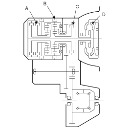
Stall speed is too high in both "D" and "R" ranges
Low line pressure
Low & reverse brake(B) slippage
Stall speed is to high in "D" range only
Underdrive clutch(C) slippage
Stall speed is too high in "R" range only
Reverse clutch(A) slippage
Stall speed too low in both "D" and "R" ranges
Malfunction of torque converter(D)
Insufficient engine output

Warm up the engine until the automatic transaxle fluid temperature is 80-100°C.
Lift up the vehicle so that the wheels are free to turn.
Connect the special tool (oil pressure gauge) to each pressure discharge port.
Measure the hydraulic pressure at each port under the conditions given in the standard hydraulic pressure table, and check that the measured values are within the standard value ranges.
If a value is outside the standard range, correct the problem while referring to the hydraulic pressure test diagnosis table.
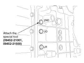
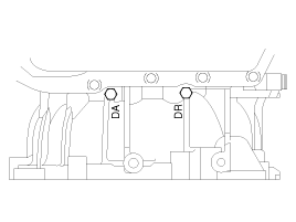
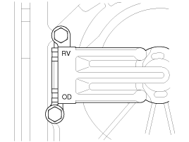
Measurement condition | Standard hydraulic pressure kPa (psi) | ||||||||
Selector lever position | Shift position | Engine speed (rpm) | Under drive clutch pressure | Reverse clutch pressure | Overdrive clutch pressure | Low&reverse brake pressure | Second brake pressure | Damper clutch Apply pressure (DA) | Damper clutch Release pressure (DR) |
P | - | 2,500 | - | - | - | 260-340 (38-50) | - | - | - |
R | Reverse | 2,500 | - | 1,270-1,770 (185-256) | - | 1,270-1,770 (185-256) | - | - | - |
N | - | 2,500 | - | - | - | 260-340 (38-50) | - | - | - |
D | 1st gear | 2,500 | 430-510 (62-74) | - | - | 1,010-1,050 (146-152) | - | - | - |
2nd gear | 2,500 | 430-510 (62-74) | - | - | - | 430-510 (62-74) | - | - | |
3rd gear | 2,500 | 430-510 (62-74) | - | 430-510 (62-74) | - | - | More than 730 (100) | 0-10 (0-1) | |
4th gear | 2,500 | - | - | 430-510 (62-74) | - | 780-880 (110-130) | More than 730 (100) | 0-10 (0-1) | |
※ The values are subject to change according to vehicle model or condition
※ Depress the acceleration pedal "GENTLY" under no load when measuring the hydraulic pressure.