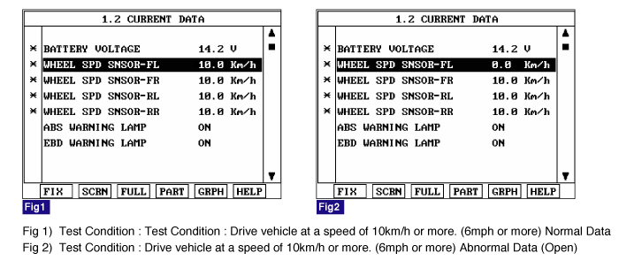
Monitor the "Wheel speed sensor" parameter on the Scantool.
Specification : Compare with another parameters related to wheel speed sensor. If it is the same as another parameters, it is in normal condition.


The wheel speed sensor is the essential component the ABS ECU uses to calculate vehicle speed and to determine whether wheel lock occurs. For example, rear wheel speed signal is used as a referecnce value, for vehicle speed, in front wheel drive vehicles, and if a difference between front and rear wheel speed occurs, then ABS control is performed. Wheel speed sensor is active hall-sensor type and good at temperature and noise chariteristic. Digital waveform is produced as tone wheel rotate according as hall sensor principle. Frequency of duty waveform is changed in proportion to rotation of tone wheel and HECU calculate vehicle speed by this frequency.
The ABS ECU monitors the wheel speed sensor circuit continuously. A direct current is supplied in the wheel-speed sensor by a power source in the input amplifier of the control unit. If the WSS circuit is broken, in that case a fault is detected by detecting abnormal input current. HECU cuts off the voltage supply to wheel sensor channel which had a fault and prevent vehicle's damage due to super heated harness. If one or more defects has detected, DTC code of defected wheel will be stored. Mutual short between sensors is detected by executing self diagnosis successively at corresponding wheel when ignition ON. Warning lamp is turned OFF unless additional faults are detected when the IG KEY is turned ON again.
Item | Detecting Condition | Possible cause | ||
DTC Strategy | ● Voltage monitoring | ● Open or short of Wheel speed sensor circuit ● Inoperative Wheel speed sensor ● Inoperative HECU | ||
Case1 | Monitoring Period | ● Once after power up. | ||
Enable Conditions | ● Shorts between WSS lines and shorts to UZ can be detected by switching single WSS channels in sequence. If there is an error after end of test, a failure is recognized. | |||
Case2 | Monitoring Period | ● Continuous | ||
Enable Conditions | ● When the sensor current levels are out of permissible range(LOW : 7 mA, HIGH : 14 mA) for 200 ms. | |||
Fail Safe | ● Sensor failure outside of the ABS control cycle
● Sensor failure inside the ABS control cycle
| |||
Engine "ON".
Connect scantool to Data Link Connector(DLC).
Start and drive vehicle in gear and maintain vehicle speed at or above 10 km/h(6 mph)
Monitor the "Wheel speed sensor" parameter on the Scantool.
Specification : Compare with another parameters related to wheel speed sensor. If it is the same as another parameters, it is in normal condition.

Is parameter displayed within specifications?

▶ Fault is intermittent caused by poor connection in wheel speed sensor harness and/or HECU's connector or was repaired and HECU memory was not cleared. Thoroughly check connectors for looseness, poor connection, bending, corrosion, contamination, deterioration, or damage. Repair or replace as necessary and then go to "Verification Of Vehicle Repair" procedure.

▶ Go to "W/Harness Inspection" procedure.
Many malfunctions in the electrical system are caused by poor harness(es) and terminals. Faults can also be caused by interference from other electrical systems, and mechanical or chemical damage.
Thoroughly check connectors for looseness, poor connection, bending, corrosion, contamination, deterioration, or damage.
Has a problem been found?

▶ Repair as necessary and then go to "Verification Of Vehicle Repair" procedure.

▶ Go to "Power Circuit Inspection" procedure.
Ignition "ON".
Measure voltage between terminal (1) of the wheel speed sensor harness connector and chassis ground.
Specification : Approx. B+

Is the measured voltage within specifications?

▶ Go to "Signal Circuit Inspection" procedure.

▶ Check for open or short to GND in wheel speed sensor harness(FL) between terminal "1" of the wheel speed sensor(FL) harness connector and terminal of the HECU harness connector. Repair as necessary and then go to "Verification Of Vehicle Repair" procedure.
▶ If OK, Substitute with a known-good HECU and check for proper operation. If problem is corrected, replace HECU and then go to "Verification Of Vehicle Repair" procedure.
DTC | LOCATION | HECU harness connector (Power supply) | |
ABS | ESP | ||
DTC C1200 | Front Left | 16 | 26 |
DTC C1203 | Front Right | 9 | 9 |
DTC C1206 | Rear Left | 6 | 6 |
DTC C1209 | Rear Right | 8 | 8 |
Lift the vehicle.
Ignition "ON".
Turn the wheel with hand.
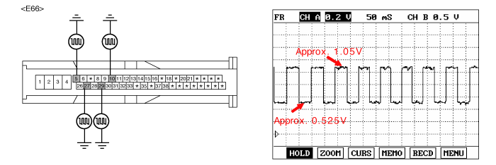
Measure waveform between terminal of the HECU harness connector and chassis ground.
Specification : Approx. High : 1.05 V , Low : 0.525 V

DTC | LOCATION | HECU harness connector (Signal) | |
ABS | ESP | ||
DTC C1200 | Front Left | 5 | 5 |
DTC C1203 | Front Right | 10 | 10 |
DTC C1206 | Rear Left | 17 | 27 |
DTC C1209 | Rear Right | 19 | 29 |
Is the measured waveform within specifications?

▶ Substitute with a known-good HECU and check for proper operation. If problem is corrected, replace HECU and then go to "Verification Of Vehicle Repair" procedure.

▶ Check for open or short to GND in wheel speed sensor harness(FL) between terminal "2" of the wheel speed sensor(FL) harness connector and terminal "5" of the HECU harness connector. Repair as necessary and then go to "Verification Of Vehicle Repair" procedure.
▶ If OK, Go to "Component Inspection" procedure.
Lift the vehicle.
Ignition "ON".
Turn the wheel with hand.
Measure waveform between terminal "1" of the wheel speed sensor harness connector and chassis ground.
Specification : Approx. High : 1.05 V , Low : 0.525 V

Is the measured waveform within specifications?

▶ Fault is intermittent caused by poor connection in wheel speed sensor harness (FL). Go to "Verification Of Vehicle Repair" procedure.

▶ Substitute with a known-good Wheel speed sensor and check for proper operation. If problem is corrected, replace Wheel speed sensor and then go to "Verification Of Vehicle Repair" procedure.
After a repair, it is essential to verify that the fault has been corrected.
Connect scantool and select "Diagnostic Trouble Codes (DTCs)" mode
Using a scantool, Clear DTC.
Operate the vehicle within DTC Detecting Condition in General Information
Are any DTCs present?

▶ Go to the applicable troubleshooting procedure.

▶ System performing to specification at this time.