
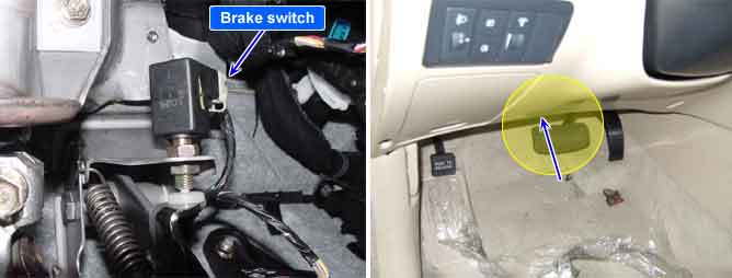
The brake light switch indicates brake pedal status to the ABS control unit. The brake light switch which is dual switch type send brake light signal to HECU. The switch is turned on when brake is depressed. The brake light switch runs to battery voltage when brake depressed. but The brake light switch doesn’t run to battery voltage when brake is not depressed. On the contrary, The brake switch is normally close type which doesn’t run to battery voltage when brake depressed.
The brake light signal is a reference to judge driver’s intention for braking and The HECU checks open or short circuit of brake light switch for normal ABS/ESP control. If the brake light switch have an error, warning ramp will be turned ON.
Item | Detecting Condition | Possible cause | |
DTC Strategy |
•
Voltage monitoring |
•
Open circuit in brake switch line
•
Faulty stop lamp switch
•
Faulty HECU | |
Case1 | Monitoring Period |
•
Continuous (only no under voltage is not detected) | |
Enable Conditions |
•
If the BLS-signals is high for 60 s, while the gas pedal is stepped, with vehicle speed > 10.8km/h, offset compensated pressure < 5 bar and no control is active, a fault is set. | ||
Case2 | Monitoring Period |
•
Continuous (only normal voltage) | |
Enable Conditions |
•
For redundancy reasons an additional BLSpVor-signal is created by the pressure sensor signal. If the pressure sensor is compensated, the threshold for generating the BLSpVor signal is 10 bar. If the pressure sensor is not compensated, the threshold is increased by 15bar. If this signal is set without any hardware-BLS-signals being set for at least 1s.
•
If the pressure signal is higher than 80bar and not both of the hardware-BLS are set, a fault is stored after 1s. | ||
Fail Safe |
•
Inhibit the ESP control and allow the ABS/EBD control.
•
The ESP warning lamps are activated. | ||