2.
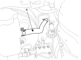
Clamp the clutch master cylinder hose(A). If there is no enough room for clamping, you can also clamp the hose from the brake master cylinder side.
[LHD]
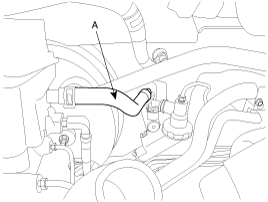
[RHD]
Do not spill brake fluid on the vehicle; it may damage the paint if brake fluid does contact the paint, wash it off immediately with water.
Remove the brake fluid fron the clutch master cylinder reservoir with a syringe.
Clamp the clutch master cylinder hose(A). If there is no enough room for clamping, you can also clamp the hose from the brake master cylinder side.
Disconnect the hose(A) from the cylinder by releasing the clutch master cylinder clamp.
Remove the ignition lock switch.
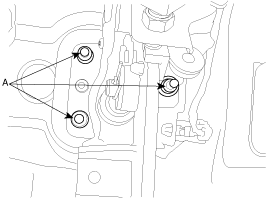
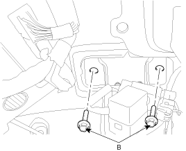
Remove the clutch pedal assembly mounting nuts (A-3ea) and bolt (B-2ea).
Remove the clutch pedal and the master cylinder assembly together.
The clutch pedal and the clutch master cylinder are supplied as an assembly.
Inspect the continuity of the ignition lock switch.
Remove the floor mat before adjusting the clutch pedal.
Installation is in reverse order of removal.
Install a new one by tightening the bolts of the clutch pedal bracket.
TORQUE :
19~26 Nm(1.9~2.6 kgf.m, 13.8~18.9 Ib-ft)
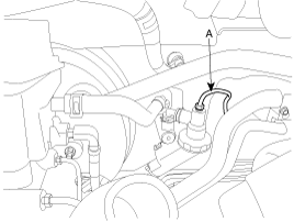
Bleed the air in C.S.C.(Concentric Slave Cylinder) system refering to ADJUSTMENT PROCEDURE.
Adjust the clutch pedal and the ignition lock switch.
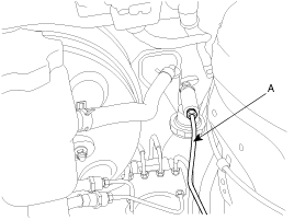
After disconnecting a cap from the concentric slave cylinder air bleeder, insert a vinyl hose in the plug.
Loosening the plug screw, press and release the clutch pedal about 10 times.
Hold the air bleeder body not to rotate with a spanner(A). The holding is needed when the plug loosened or tightened.
Tighten the plug during the clutch pedal pressed. Afterwards, raise the pedal with a hand.
TORQUE :
25~29Nm (2.5~2.9Kgf.m, 18.2~21.1lb-ft)
After pressing the clutch pedal 3 times more, loosen the plug and retighten it with the pedal pressed. Raise it again, then.
Repeat the step 4 two or three times. (until there is no bubble in the fluid)
Do not clamp the pipe of a concentric slave cylinder.
Be careful not to damage O-rings.
Inspect a ignition lock switch.
Remove the driver's seat mat to adjust a clutch pedal.
No gap between a clutch master cylinder pistion and push rod can cause clutch slip.
Loosen and draw out the bolt until it is off the pedal surface.
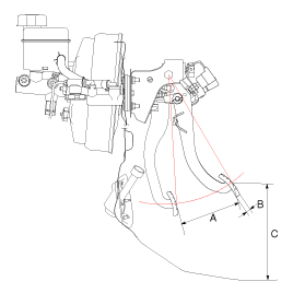
Push and pull a clutch master cylinder push rod to satisfy the specification below.
Specification [mm(in)]
Clutch pedal stroke(A) - 150~155(5.98~5.99)
Clutch pedal free play(B) - 6~13(0.24~0.51)
Clutch pedal distance(C) - 234.7(9.24)
With no pressure on a clutch pedal, tighten the bolt until it contacts on the pedal.
Fix the bolt with a nut.
TORQUE :
14~20Nm (1.4~2.0kgf.m, 10.2~14.5lb-ft)
Press the clutch pedal to the seat ground.
Adjust the ignition lock switch position with the pedal a little(23~26mm) raised.
Install the ignition lock switch firmly.
TORQUE:
8~10Nm (0.8~1.0kgf.m, 5.8~7.2lb-ft)
Disconnect 2P-connector from a ignition lock switch.
Disconnect the ignition lock switch. (if you can install a tester with the switch fixed, this step can be omissible)
Check for continuity between terminals. (refer to the table below)
Clutch pedal position | Ignition lock switch | Continuity |
Released | Released | NO |
Pressed | Pressed | YES |
If there is difference between what tested and the table above, replace the ignition lock switch with a new one.
If not, install the ignition lock switch and adjust the clutch pedal.
TORQUE :
8~10Nm (0.8~1.0kgf.m, 5.8~7.2lb-ft)
