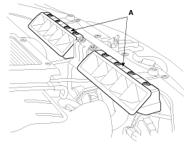
1.
Remove the air duct(A).
Make sure jacks and safety stands are placed properly.
Make sure the vehicle will not roll off stands and fall while you are working under it.
Use fender covers to avoid damaging painted surface.
Unplug the wiring connectors carefully while holding the connector portion to avoid damage.
Mark all wiring and hoses to avoid misconnection.
Also, be sure that they do not contact other wiring or hoses or interfere with other parts.
Remove the air duct(A).
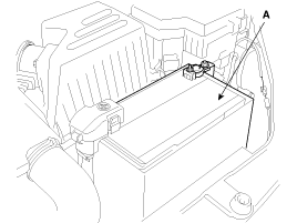
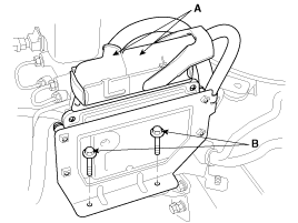
Remove the battery terminals and the battery assembly(A).
Remove the intercooler system.
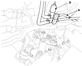
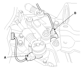
Disconnect the connector(C) related to the BPS(Boost Pressure Sensor)(A) and the VGT(Variable Geometry Turbocharger) solenoid valve(B).
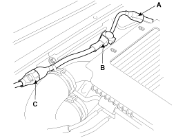
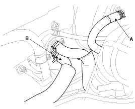
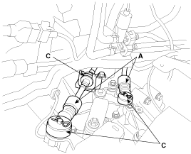
Disconnect the intercooler hoses(A).
Disconnect the VGT(Variable Geometry Turbocharger) solenoid valve vaccum hoses(B).
Remove the intercooler hose assembly(C).
Tightening torque :
7.8 ~ 11.8N.m(0.8~1.2kgf.m, 5.8 ~ 8.7lb-ft)
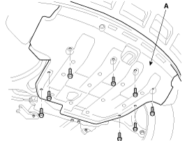
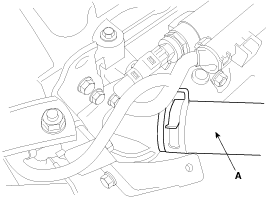
Remove the under cover(A).
Drain engine coolant and remove the radiator cap to speed draining.
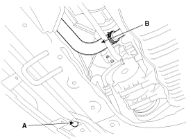
Remove the drain plug(A) and the radiator lower hose(B).
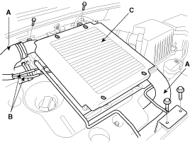
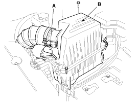
Remove the air cleaner assembly.
Disconnect the AFS(Air Flow Sensor) connector(A).
After removing the air intake hose clamp, loosen the air cleaner assembly mounting bolts(2EA).
Remove the air cleaner assembly(B).
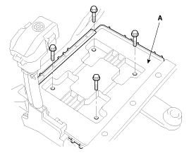
Remove the battery tray(A), loosening the mounting bolts(4EA).
Disconnect the ECU(Engine Control Unit) connectors(A) and remove its mounting bolts(B).
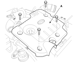
Remove the engine cover(A).
Remove the hose between the intercooler and the intake system.
Remove the engine wirings.
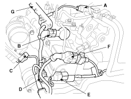
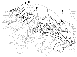
Disconnect the rail pressure sensor connector(A) and the ECT(Engine Coolant Temperature) sensor connector(B).
Disconnect the camshaft position sensor connector(A), the rail pressure regulator connector(B), the swirl valve actuator connector(C), the electronic throttle body actuator connector(D), the oil pressure switch connector(E) and the crankshaft position sensor connector(F) and remove the connector/wire harness protector(G).
Disconnect the EGR(Exhaust Gas Recirculation) solenoid valve connector(A), the glow plug(B), the fuel pressure regulator valve connector(C), the injector(D) and the connector/wire harness protector(E).
Disconnect the ground lines(F).
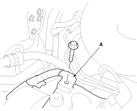
Disconnect the ground line from the cylinder head(A).
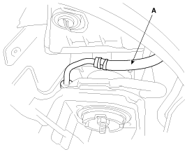
Remove the fuel hose(A) and the fuel temperature sensor connector(B).
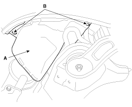
Disconnect the brake booster vacuum hose(A) and the heater hoses(B).
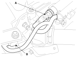
Disconnect the upper radiator hose(A).
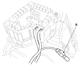
Disconnect the battery cables to the fuse & relay box by removing the nuts.
Disconnect the front lamp connector(B).
Remove the wirings related to the transaxle.
Disconnect the back up lamp switch connector(A).
Disconnect the neutral switch connector(B).
Disconnect the vehicle speed sensor.
Remove the shift cable assembly(A), the clip(B) and the pin(C).
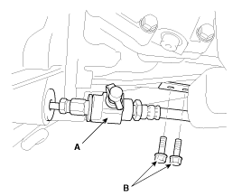
Remove the concentric slave cylinder with clamping the tube(A).
Remove the groung line mounting bolts(B) from the transaxle.
Drain power steering oil.
Disconnect the power steering oil hose(A).
Remove the clips(B) from the right side wheel guide(A).
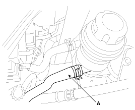
Disconnect the power steering lower hose(A).
Recover air-conditioning refrigerant and remove the high & low pressure hoses.(Refer to 'HA' group).
Remove the steering column universal joint mounting bolt(A).
Disconnect the EPS(Electronic Power Steering) sensor connector(B).
Remove the front wheels and tires.
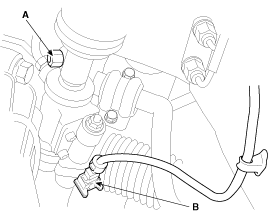
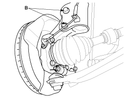
Remove the wheel speed sensor(A).(Refer to 'SS' group).
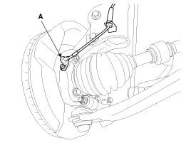
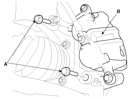
After removing the mounting bolts(A) and the caliper(B), bind it up to the coil spring of the strut.
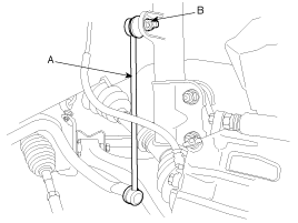
Remove the strut assembly by removing the stabilizer bar(A) link nuts(B) and the strut lower mounting bolts(B).(Refer to 'SS' group).
Remove the front muffler(A).
Tightening torque :
39.2 ~ 58.8N.m(4.0 ~ 6.0kgf.m, 28.9 ~ 43.4lb-ft)
Disconnect the propeller shaft(A).(Refer to 'DS' group).
Tightening torque :
49.0 ~ 68.6N.m(5.0 ~ 7.0kgf.m, 36.2 ~ 50.6lb-ft)
The propeller shaft is tightened by left-handed screw bolts.
Install a jack under the engine and transaxle assembly for supporting.
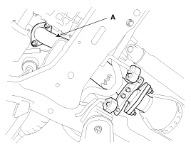
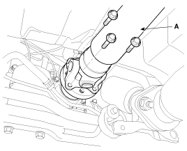
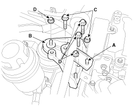
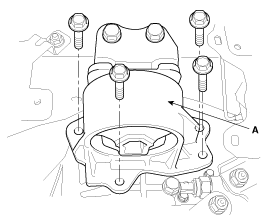
Remove the engine stay(A) and the engine mounting bracket(B).
Tightening torque :
Bolts, Nut(C): 39.2 ~ 53.9N.m(4.0 ~ 5.5kg.m, 28.9 ~ 39.8lb-ft)
Bolts, Nut(D): 63.7 ~ 83.4N.m(6.5 ~ 8.5kg.m, 47.0 ~ 61.5lb-ft)
Remove the transaxle mounting(A).(Refer to 'MT/AT' group).
Remove the subframe mounting bolts and nuts.
Tightening torque :
Bolts, Nuts: 68.6 ~ 88.3N.m(7.0 ~ 9.0kg.m, 50.6 ~ 65.1lb-ft)
Bolts: 137.3 ~ 156.9N.m(14.0 ~ 16.0kg.m, 101.3 ~ 115.7lb-ft)
Remove the engine and transaxle assembly by lifting the vehicle.
When removing the engine and transaxle assembly, be careful not to damage any surrounding parts or body components.
Installation is in the reverse order of removal.
Perform the following :
Adjust the shift cable.
Adjust the throttle cable.
Refill the engine with engine oil.
Refill the transaxle with fluid.
Refill the radiator and reservoir tank with engine coolant.
Place the heater control knob on “HOT” position.
Bleed air from the cooling system.
- Start engine and let it run until it warms up. (until the radiator fan operates 3 or 4 times.) - Turn Off the engine. Check the level in the radiator, add coolant if needed. This will allow trapped air to be removed from the cooling system. - Put the radiator cap on tightly, then run the engine again and check for leaks. |
Clean the battery posts and cable terminals with sandpaper assemble them, then apply grease to prevent corrosion.
Inspect for fuel leakage.
- After assemble the fuel line, turn on the ignition switch (do not operate the starter) so that the fuel pump runs for approximately two seconds and fuel line pressurizes. - Repeat this operation two or three times, then check for fuel leakage at any point in the fuel line. |
