3.
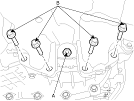
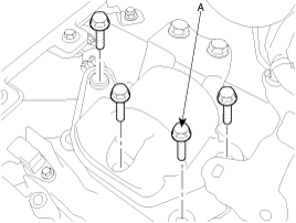
Install the drive plate bolts (A) by turning the timing gear.
TORQUE:
46~53 Nm(4.6~5.3 kgf.m, 33.3~38.3 lb-ft)
Installation is in the reverse order of removal.
Perform the following :
Adjust the shift cable.
Refill the transaxle with fluid.
Refill the radiator with engine coolant.
Bleed air from the cooling system with the heater valve open.
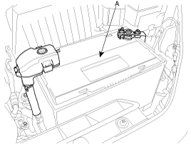
Clean the battery posts and cable terminals with sandpaper, assemble them, and apply grease to prevent corrosion.
Lowering the vehicle or lifting up a jack, install the transaxle assembly.
Tighten the transaxle lower mounting bolts (B-4EA).
TORQUE:
65~85 Nm(6.5~8.5 kgf.m, 47.0~61.5 lb-ft)
Install the drive plate bolts (A) by turning the timing gear.
TORQUE:
46~53 Nm(4.6~5.3 kgf.m, 33.3~38.3 lb-ft)
In case of 4WD, install the transfer case assembly. (see MT group's 'Transfer case')
After removing a jack, insert the drive shafts. (see DS group)
Install the sub frame. (see SS group).
Tighten the roll stopper mounting bolts.
TORQUE:
90~110 Nm(9~11 kgf.m, 65.1~79.5 lb-ft)
Connect the lower arm, the tie rod end ball joint, the stabilizer bar link to the front knuckle. (see SS group)
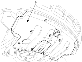
Install the under cover (A).
Install the steering column joint bolt and the EPS connector. (see ST group)
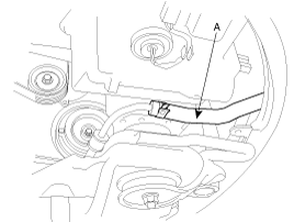
Connect the return tube(A) with a clamp. (see ST group)
Install the front wheels and tires.
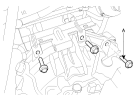
Tighten the transaxle insulator mounting bolt (A).
TORQUE:
90~110 Nm(9~11 kgf.m, 65.1~79.5 lb-ft)
Tighten the transaxle mounting bolts (A).
TORQUE:
65~85 Nm(6.5~8.5 kgf.m, 47.0~61.5 lb-ft)
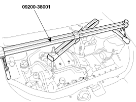
Remove the SST (09200-38001) holding the engine and transaxle assembly.
Install the starter motor. (see EE group).
TORQUE:
65~85 Nm(6.5~8.5 kgf.m, 47.0~61.5 lb-ft)
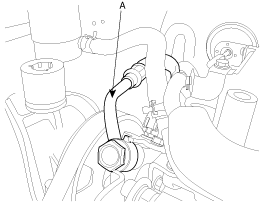
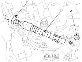
Connect the power steering pressure tube (A) to the power steering oil pump.
Connect the transaxle oil cooler hoses (A) to the tubes by fastening the clamps (B).
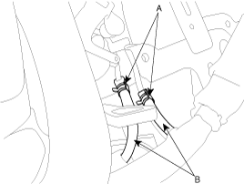
Install the control cable assembly(C) by tightening the nut (A) and clip (B).
TORQUE:
8~12 Nm(0.8~1.2 kgf.m, 5.8~8.6 lb-ft)
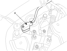
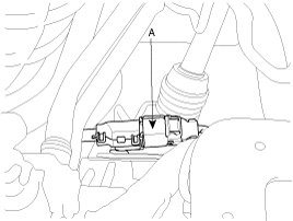
Connect the transaxle wire harness connectors.
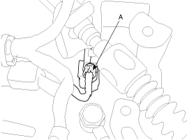
Install the inhibiter switch connector (A).
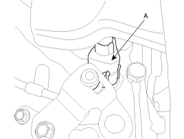
Install the solenoid valve connector (A).
Install the input speed sensor connector (A).
Install the output speed sensor connector (A).
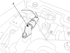
Install the vehicle speed sensor connector (A).
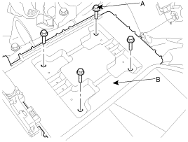
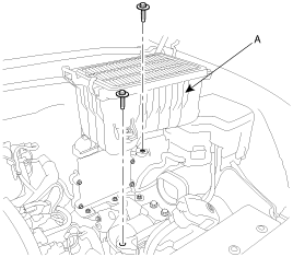
Install the battery tray (B) by tightening the four mounting bolts (A).
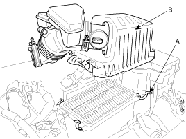
Install the air cleaner lower part (A) by installing the two mounting bolts.
Install the air cleaner upper cover (B) by installing the clips (A).
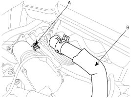
Connect the air cleaner hose (B) and tighten the clamp bolt (A).
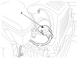
Connect the AFS connector (A).
Install the battery (A).
Refill the transaxle fluid. (see 'Service adjustment procedure')
Refill the power steering fluid. (see 'ST' group)
After installing the inter cooler assembly, bleed the air in the system.
Install the engine cover and the inter cooler assembly. (see 'EM' group)
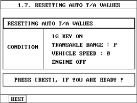
When replacing the automatic transaxle, reset the automatic transaxle's values by using the High- Scan Pro.
Connect the Hi-Scan Pro connector to the data link connector under the crash pad and power cable to the cigar jack under the center facia.
Turn the ignition switch on and power on the Hi-Scan Pro.
Select the vehicle's name.
Select 'AUTOMATIC TRANSAXLE'.
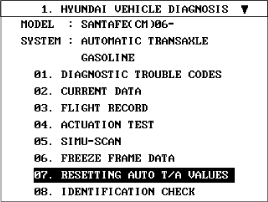
Select 'RESETTING AUTO T/A VALUES' and perform the procedure.
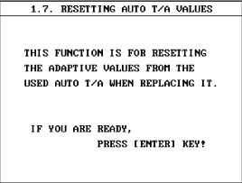
Perform the procedure by pressing F1 (REST).