
The cruise control system keeps the vehicle running at a fixed speed until a signal canceling this fixed speed is received. When the main switch is turned on with vehicle in the running mode, the battery voltage is applied to the PCM. When a signal from the control switch is input to the PCM while the vehicle is in state, the PCM controls fuel injection to make a car go at a steady speed you want. Also, while the system is operating, "CRUISE" indicator lamp in the meter assembly lights up.
If the switch signal's voltage is not within the calibrated ranges when PCM checks the switch signal under detecting condition, PCM sets P0564.
Item | Detecting Condition | Possible Cause | |
DTC Strategy | Case1 |
•
Invalid voltage range check |
•
Open or short in harness
•
Poor connection or damaged harness
•
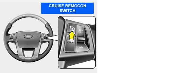
Faulty cruise remote control switch |
Case2 |
•
Check SET/COAST switch stuck | ||
Case3 |
•
Check RES/ACC switch stuck | ||
Enable Conditions | Case1 |
•
10V < Battery voltage <16V | |
Case2 & 3 |
•
10V < Battery voltage <16V
•
Cruise control not active | ||
Threshold Value | Case1 |
•
0.05 V < Switch voltage(SW) < 0.72 V or 0.85V < SW <2 V or 2.2 V < SW < 4.4 V or 4.8 V < SW | |
Case2 |
•
0.72 V < Switch voltage < 0.85V | ||
Case3 |
•
2.0V < Switch voltage < 2.2V | ||
Diagnostic Time | Case1 |
•
31sec. | |
Case2 |
•
61sec. | ||
Case3 |
•
61sec. | ||
MIL On Condition |
•
- | ||
Item | Resistance(Ω) | Item | Resistance(Ω) |
CRUISE MAIN switch | 3.9 kΩ ± 5% | COAST SET switch | 220 Ω ± 5% |
CANCEL switch | 0 Ω ± 5% | RESUME/ACCEL switch | 910 Ω ± 5% |