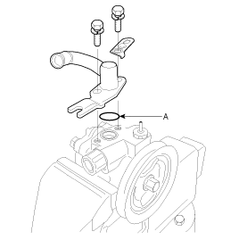
Remove the intercooler assembly. (Diesel only, refer to EM group)
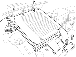
Remove the intercooler assembly. (Diesel only, refer to EM group)

Remove the drive belt.
Remove the alternator. (Diesel only, refer to EE group)
Disconnect the oil pressure switch.
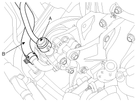
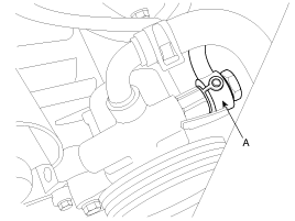
Disconnect the pressure tube (A) and suction hose (B) from the power steering pump assembly.
Tightening torque
: 55 ~ 65Nm (5.5 ~ 6.5kgf.m, 40 ~ 47lb-ft)
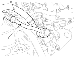
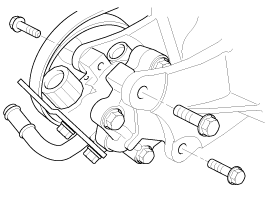
Loosen the power steering pump mounting bolt and nut, and then remove the power steering pump assembly from the pump bracket.
Tightening torque
: 17 ~ 26Nm (1.7 ~ 2.6kgf.m, 12 ~ 19lb-ft)
Tightening torque
: 35 ~ 50Nm (3.0 ~ 5.0kgf,m, 25 ~ 36lb-ft)
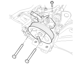

Be careful not to spill the fluid from the power steering oil pump.
Installation is the reverse of removal.
Be sure to connect between a tube and a hose as shown in the illustration.
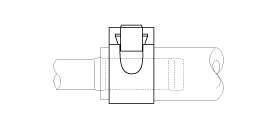
The pressure tube does not twist and come in contact with other components.
Add the power steering fluid.
Bleed the power steering system. (Refer to the air bleeding in ST-group)
Check the oil pump pressure. (Refer to the oil pump pressure test in ST-group)
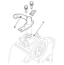
Remove two bolts from the oil pump body (A), and then remove the suction pipe (B) and O-ring.
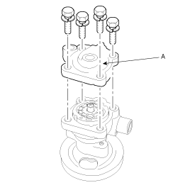
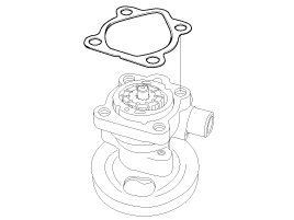
Loosen the four bolts and remove the oil pump cover assembly (A) and the gasket.
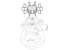
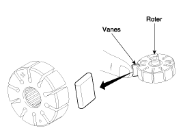
Remove the rotor and vanes.
Remove the cam ring.
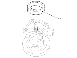
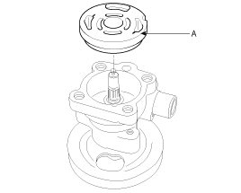
Remove the oil pump side plate (A).
Remove the inner and outer O-ring (A).
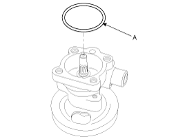
When assembling, use a new gasket and O-ring.
Mount the pump in a vise and remove the pulley (A) nut and the spring washer.
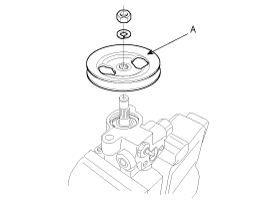
After removing the snap ring (A) of the shaft with snap ring pliers, remove the dust spacer.
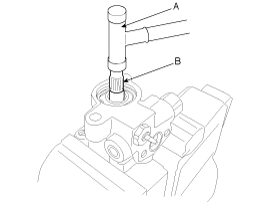
Tap the rotor side of the shaft slightly with a plastic hammer (A) to remove the shaft (B).
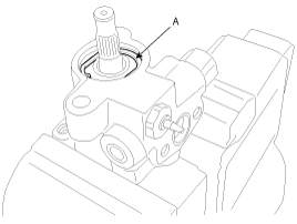
Remove the oil seal from the oil pump body.
When assembling, use a new oil seal.
Remove the connector from the oil pump body, and take out the flow control valve (A) and the flow control spring (B).
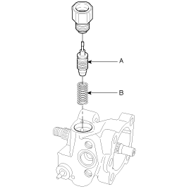
Remove the O-ring from the connector.
Do not disassemble the flow control valve.
Check that the flow control valve is not bent.
Check the shaft for wear and damage.
Check the V belt for wear and deterioration.
Check the grooves of the rotor and vanes for stratified abrasion.
Check the contact surface of the cam ring and vanes for stratified abrasion.
Check vanes for damage.
Check that there is no striped wear in the side plate or contacting part between the shaft and the pump cover surface.
Install the flow control spring (B), the flow control valve (A) and the connector into the pump body.

Install the oil seal in the pump body by using the special tool (09222-32100).
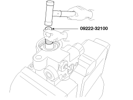
After inserting the shaft assembly into the pump body, install the dust spacer and snap ring (A).

Install the pump pulley(A).
Tightening torque
: 55 ~ 69Nm (5.5 ~ 6.9kgf·m, 39.8 ~ 49.9lb-ft)

Install the inner O-ring and outer O-ring (A).

Install the oil pump side plate (A).

After inserting the lock pin into the groove of the front housing, install the camring (A) attending to the direction.

Install the rotor and the vanes.

Install the gasket and oil pump cover assembly (A).
Tightening torque
: 15.3 ~ 20.2Nm (1.56 ~ 2.04kgf.m, 11.3 ~ 14.9lb-ft)
Install the O-ring (A) and the suction pipe mounting bolt.
Tightening torque
: 13.6 ~ 18.4Nm (1.36 ~ 1.84kgf.m, 9.84 ~ 13.3lb-ft)
