Thoroughly clean all parts to be assembled.
Always use a new cylinder head and manifold gasket.
Always use a new cylinder head bolt.
The cylinder head gasket is a metal gasket. Take care not to bend it.
Rotate the crankshaft, set the No.1 piston at TDC.
Clean the gasket mating surfaces of the cylinder head and block to remove oil, dust and scratches.
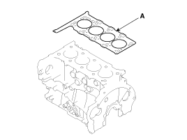
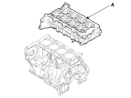
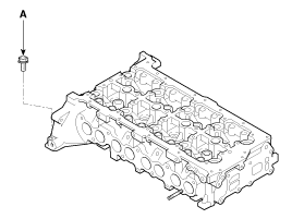
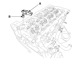
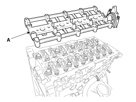
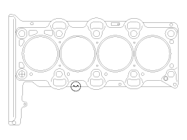
Select the cylinder head gasket.
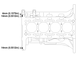
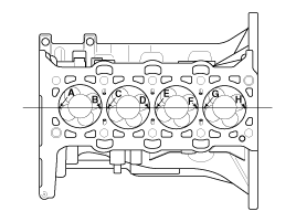
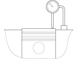
Measure the piston protrusion from the upper cylinder block face on 8 places (A ~ H) at TDC.
Measure on the crankshaft center line considering the piston migration.
Select the gasket in the table below using the average value of piston protrusions. Although even the only 1 point is over than the each rank limit, use 1 rank upper gasket than specified in the table below.
Displacement | 2.0L/2.2L | ||
Average of piston protrusion | 0.410 ~ 0.531mm (0.0161 ~ 0.0209in) | 0.531 ~ 0.602mm (0.0209 ~ 0.0237in) | 0.602 ~ 0.672mm (0.0237 ~ 0.0265in) |
Gasket thickness | 1.15 ~ 1.25mm (0.0453 ~ 0.0492in) | 1.25 ~ 1.35mm (0.0492 ~ 0.0531in) | 1.35 ~ 1.45mm (0.0531 ~ 0.0571in) |
Limit of each rank extant | 0.581mm (0.0229in) | 0.652mm (0.0257in) | 0.722mm (0.0284in) |
Identification code | ![]() | ![]() | ![]() |
Install the cylinder head gasket (A) on the cylinder block.
Apply sealant on cylinder block top face before assembling cylinder head gaskets and apply sealant on cylinder head gaskets after assembling cylinder head gaskets on cylinder block.
Apply sealant (LOCTITE 5902 or equivalent) and assemble the cylinder head within 15 minutes.
Seat the cylinder head gasket on the cylinder head firmly.
Be careful not to damage the bead and coating of the cylinder head gasket before and after assembling the cylinder head gasket.
Place the cylinder head (A) quietly in order not to damage the gasket with the bottom part of the end.
Install the cylinder head bolts.
Do not apply engine oil on the cylinder head bolts.
Using SST(09221-4A000), install and tighten the 10 cylinder head bolts, in several passes, in the sequence shown.
Tightening torque :
78.5N.m (8.0kgf.m, 57.9lb-ft) + 120° + 120°
Do not reuse the cylinder head bolts.
Install the cylinder head side bolt (A).
Tightening torque :
30.4 ~ 34.3N.m (3.1 ~ 3.5kgf.m, 22.4 ~ 25.3lb-ft)
Install the hydraulic lash adjuster (HLA) (B) and cam follower (A).
Until installing HLA shall be held upright so that engine oil in HLA should not spill and assured that dust does not adhere to HLA.
HLA shall be inserted tenderly to the cylinder head not to spill engine oil from HLA. In case of spilling, air bent shall be done in accordance with the air bent procedure.
Stroke HLA in engine oil 4~5 times by pushing its cap while pushing the ball down slightly by hard steel wire. (Take care not to severely push hard steel wire down since ball is several grames.)
Install the cam carrier (A) with a new gasket.
Apply sealant (LOCTITE 518, THREEBOND 1389 or equivalent) to the rectangular area at the rear of the cylinder head before assembling the cam carrier.
Remove the extruded sealant after assembling cam carrier.
Install the camshafts (A) with the timing marks (B,C) aligned.
When assembling the camshafts, check the front amd rear timing marks on the gears.
Install the camshaft bearing caps (A).
Tightening torque :
10.8 ~ 12.7N.m (1.1 ~ 1.3kgf.m, 8.0 ~ 9.4lb-ft)
Remove the assembly pin (B). (Standard only)
Install the vacuum pump (A) with a new O-ring (B).
Tightening torque :
10.8 ~ 14.7N.m (1.1 ~ 1.5kgf.m, 8.0 ~ 10.8lb-ft)
Be careful not to miss the O-ring out of the vacuum pump before installing the vacuum pump.
Install the glow plug (A) and the wiring & glow plug plate (B).
Tightening torque :
Glow plug : 15 ~ 20N.m (1.5 ~ 2.0kgf.m, 11 ~ 14lb-ft)
Plate nut : 0.8~1.5N.m (0.08 ~ 0.15kgf.m, 0.6 ~ 1.1lb-ft)
Install the common rail (A). (Refer to FL group)
Tightening torque :
19.6 ~ 26.5N.m (2.0 ~ 2.7kgf.m, 14.5 ~ 19.5lb-ft)
Install the timing chain. (Refer to Timing chain in this group)
Install the intake and exhaust manifold. (Refer to Intake ad exhaust system in this group)