3.
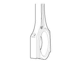
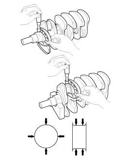
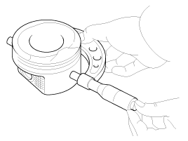
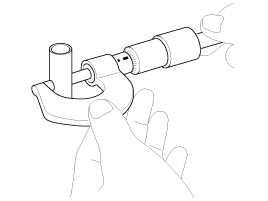
Using a connecting rod aligning tool, check the rod for bend and twist. If the measured value is close to the repair limit, correct the rod by a press. Any connecting rod that has been severely bent or distorted should be replaced.
Allowable bend of connecting rod :
0.05mm / 100mm (0.0020 in./3.94 in.) or less
Allowable twist of connecting rod :
0.1mm / 100mm (0.0039 in./3.94 in.) or less
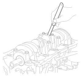
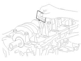
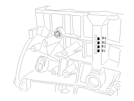
Crankshaft bore mark location
Letters have been stamped on the block as a mark for the size of each of the 5 main journal bores.
Use them, and the numbers or bar stamped on the crank (marks for main journal size), to choose the correct bearings.
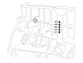
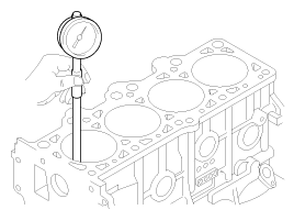
Discrimination Of Cylinder Block
Calss | Mark | Inside Diameter |
a | A | 56.000 ~ 56.006mm (2.2047 ~ 2.2049in.) |
b | B | 56.006 ~ 56.012mm (2.2049 ~ 2.2052in.) |
c | C | 56.012 ~ 56.018mm (2.2052 ~ 2.2054in.) |
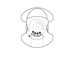
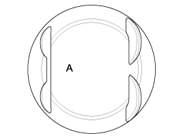
Crankshaft Journal Mark Location Discrimination Of Crankshaft
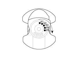
note
Conform to read stamping order as shown arrow direction from #1.
Discrimination Of Crankshaft
Class | Mark | Outside Diameter Of Journal |
I | 1 | 51.954 ~ 51.960mm (2.0454 ~ 2.0456in.) |
II | 2 | 51.948 ~ 51.954mm (2.0452 ~ 2.0454in.) |
III | 3 | 51.942 ~ 51.948mm (2.0449 ~ 2.0452in.) |
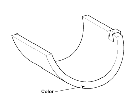
Place Of Identification Mark (Crankshaft Bearing) Discrimination Of Crankshaft Bearing
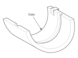
Discrimination Of Crankshaft Bearing
Class | Mark | Thickness Of Bearing |
AA | Blue | 2.026 ~ 2.029mm (0.0797 ~ 0.0798in.) |
A | Black | 2.023 ~ 2.026mm (0.0796 ~ 0.0797in.) |
B | None | 2.020 ~ 2.023mm (0.0795 ~ 0.0796in.) |
C | Green | 2.017 ~ 2.020mm (0.0794 ~ 0.795in.) |
D | Yellow | 2.014 ~ 2.017mm (0.0793 ~ 0.0794in.) |
Selection
Crankshaft Identification Mark | Crankshaft Bore Identification Mark | Assembling Classification Of Bearing |
I (1) | a (A) | D (Yellow) |
b (B) | C (Green) |
c (C) | B (None) |
II (2) | a (A) | C (Green) |
b (B) | B (None) |
c (C) | A (Black) |
III (3) | a (A) | B (None) |
b (B) | A (Black) |
c (C) | AA (Blue) |