IG key OFF.
Place oscilloscope probe at terminal 3(CAN High) and terminal 11(CAN low) of 'DATA LINK CONNECTOR' (DLC).
Disconnect only one ECU connector as the others connected.
IG key ON.
Compare the signal waveform with reference signal waveform.
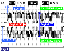
Fig.1) CAN communication waveform
☞ Different from "Signal Waveform & Data", if 1) both CAN HIGH and LOW signal are fixed at 2.5 V or 2) HIGH and LOW signal are fixed at 3.5 V and 1.5 V, respectively, it is due to communication error between connected modules.
Is there any module which shows normal signal waveform with disconnecting connector or shows abnormal signal waveform with connecting connector ?
![]() | ▶ Replace abnormal module and then, go to 'Verification of Vehicle Repair" procedure. |
![]() | ▶ Go to "Verification of Vehicle Repair" procedure. |