
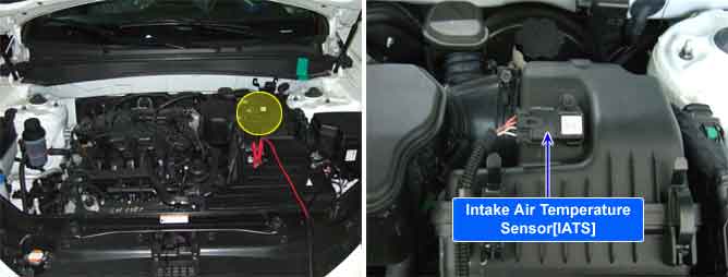
The Intake Air Temperature Sensor (IATS) is installed into the Mass Air Flow Sensor (MAFS). The IATS uses a thermistor whose resistance changes with the temperature. The electrical resistance of the IATS decreases as the temperature increases, and increases as the temperature decreases. The 5 V power source in the ECM is supplied to the IATS via a resistor in the ECM. That is, the resistor in the ECM and the thermistor in the IATS are connected in series. When the resistance value of the thermistor in IATS changes according to the intake air temperature, the signal voltage also changes. Using this signal, the information of the intake air temperature, the ECM corrects basic fuel injection duration and ignition timing.
ECM monitors temperature difference between MAX. and MIN IATS in order to detect movement in IATS not only Start Test but Drive Test while enable condition is met. If ECM detects intake air temperature changes less than 5.4 °F. ECM determines that a fault exists and a DTC is stored. ECM monitors temperature changes resulting from soaking the vehicle. Therefore, Coolant temperature and Intake temperature should be changed. If ECM detects intake air temperature correlated to coolant temperature does not change ECM determines that a fault exists and a DTC is stored.
Item | Detecting Condition | Possible cause | |
DTC Strategy | Case1 |
•
Monitors the difference between the startup coolant and IAT values |
•
Faulty IATS |
Case2 |
•
Monitors the difference between the startup IAT and coolant values | ||
Case3 |
•
Start Test: Monitors the difference between max and min IAT in order to detect movement in IAT for a certain time.
•
Drive test: Performs the max and min delta check while driving under load for a length of time followed by an idle for a certain time. | ||
Enable Conditions | Case1 |
•
Engine soaked time ≥ 360min
•
Engine running state
•
No faults present
•
IAT stored previous trip
•
Startup Coolant Temperature > -20°C
•
Airflow > 15 g/s
•
Vehicle speed > 40kph | |
Case2 |
•
Engine soaked time ≥ 360min
•
Engine running state
•
No faults present
•
IAT stored previous trip
•
Airflow > 15 g/s
•
Vehicle speed > 40kph | ||
Case3 |
•
Engine soaked time > 360min
•
Engine Running State
•
No fault present
•
IAT stored previous trip
•
No IAT Tests pending | ||
Threshold value | Case1 |
•
Startup Coolant - Startup IAT ≥ 22°C | |
Case2 |
•
Startup IAT - Startup Coolant ≥ 17°C | ||
Case3 |
•
Max IAT - Min IAT ≤ 3℃(5.4 °F) | ||
Diagnosis Time | Case1, 2 |
•
Continuous (More than 1.25 second failure) | |
Case3 |
•
Continuous (10 min.) | ||
MIL On Condition |
•
NO MIL ON(DTC only) | ||
Temp. (℃) | Resistance (kΩ) | Temp. (℃) | Resistance (kΩ) |
-40 | 40.93 ~ 48.35 | 20 | 2.31 ~ 2.57 |
-20 | 13.89 ~ 16.03 | 40 | 1.08 ~ 1.21 |
0 | 5.38 ~ 6.09 | 60 | 0.54 ~ 0.66 |
10 | 3.48 ~ 3.90 | 80 | 0.29 ~ 0.34 |
Fig.1) Normal waveform of IATS
Fig.2) Normal data of IATS & ECTS & EOTS at ig on
Fig.3) Normal data of IATS & ECTS & EOTS after warming up.
The output signals of IATS & ECTS change smoothly without any rapid changes. These 2 sensor have almost the same characteristic signal during the early period after start. It means that the temperatures of intake air and engine coolant are depended on the temperature of atmosphere. Meanwhile, During engine warm up the output signal of the ECT will change quicker than the IAT signal. even it may not change almost.