
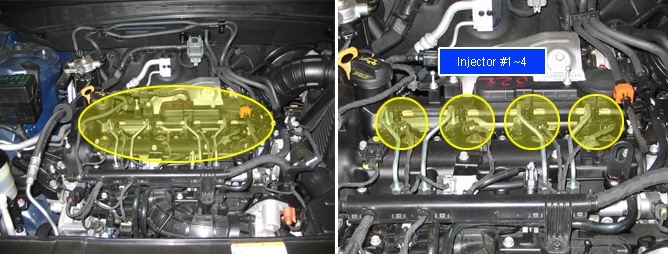
ECM controls injection amount and injection timing through Electrical control injector in order to control system pressure which is required for measuring and injection of diesel fuel. Injectors on CRDi injects atomized fuel with highly pressurized directly into the combustion chamber corresponding to fuel amount ECM decided. Fuel injected into combustion chamber generates power through the explosion.
There are 3 different fuel injection. Pilot & post injection is used for reducing explosion noise during fuel control and main injection is used for generating power. In addition, those are controlled independently by ECM and injection time (injection amount) as well. Injector is newly adopted new technology. that are hydraulic coupler which transfer operating force of actuator as quickly as possible and PIEZO actuator what is operating response better than solenoid actuator. Both PIEZO actuator and hydraulic coupler realized to increase the fuel pressure to 250 ~ 1600bar. That makes high combustion efficiency resulting to reduced smog and improved engine power and fuel efficiency.
Inputting IQA code of injectors installed in each cylinder to ECM, ECM recognizes the fuel injection quantity difference between each injectors. ECM adjusts every injector to have same fuel injecting characteristic as recognizing specific fuel injection map which is different for each serial number.
【IQA, Injector Quantity Adjustment】IQA means adjusting fuel injection quantity difference between injectors which occurs inevitably at manufacturing process as allotting serial number consists of 7 letters to each injectors.
DTC P0201 is set when no current is detected in "High side" circuit or "Low side" circuit of injector #1 at injection condition. This code is due to open in injector #1circuit / injector component.
Item | Detecting Condition | Possible Cause | ||
DTC Strategy |
•
Current Monitoring |
•
Injector circuit
•
Injector component | ||
Enable Conditions |
•
IG key ON | |||
Threshold Value |
•
Open in High side circuit.
•
Open in Low side circuit. | |||
Diagnostic Time |
•
Immediately | |||
Fail Safe | Fuel cut | NO |
•
MIL is blinking if no IQA inputted. | |
EGR Off | NO | |||
Fuel Limit | YES | |||
Check Lamp | ON | |||
Control Type | Component Resistance | Operating Voltage |
PIEZO voltage control | 150 ~250 kΩ (20℃) | 100V ~ 200V(100V ~ 140V at 250bar) |
Fig.1) Injeciton signal waveform at idle
Fig.2) Injeciton signal waveform at acceleration
Fig.3) High & Low control signal at idle