
The body electrical system is comprised of four ECU applied CAN*¹ communication nodes.
※ Body CAN communication Control Units : BCM(Body Control Module), CLU(Cluster), PDM(Power Distribution Module), SMK(Smart Key), RPAS(Rear Parking Assist System).
*¹ CAN(Controller Area Network) : CAN is serial bus communication type which links not only communication system but also control units each other.
*² LIN(Local Interconnect Network) : LIN is serial communication type which is used in electrical control system. (This is less expensive.)
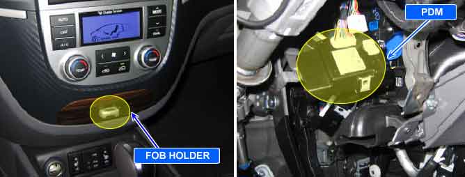
After insert the fob into the fob holder, press SSB button. Then, the communication state between the fob and the immobilizer is inputted to PDM.
This code is outputted when the immobilizer data circuit is shorted to ground.
(In this case, it is not possible to get authorization although the fob is in the holder.)
Item | Detecting Condition | Possible Cause |
DTC Strategy |
•
Immobilizer data line check (by voltage monitoring) |
•
Short to ground in immobilizer data circuit |
Enable Conditions |
•
The communication state between the fob and the fob holder when SSB button is pushed. (The fob is in the holder.) | |
Threshold Value |
•
Short to ground in immobilizer data circuit (2V and below) | |
Diagnostic Time |
•
Immediately | |
DTC Erasing Time |
•
DTC is erased immediately after trouble fixed. (After communication recovery) |
Fig.1) IMMO_CLOCK & IMMO_DATA signal waveform