As the Piezo-Injector operates under maximum DC 200V, there may be a risk of an electric shock caused by shorted control line etc. So when repairing the injector or its wiring, disconnect the battery negative (-) terminal from the battery and wait for about 30 seconds.
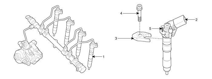
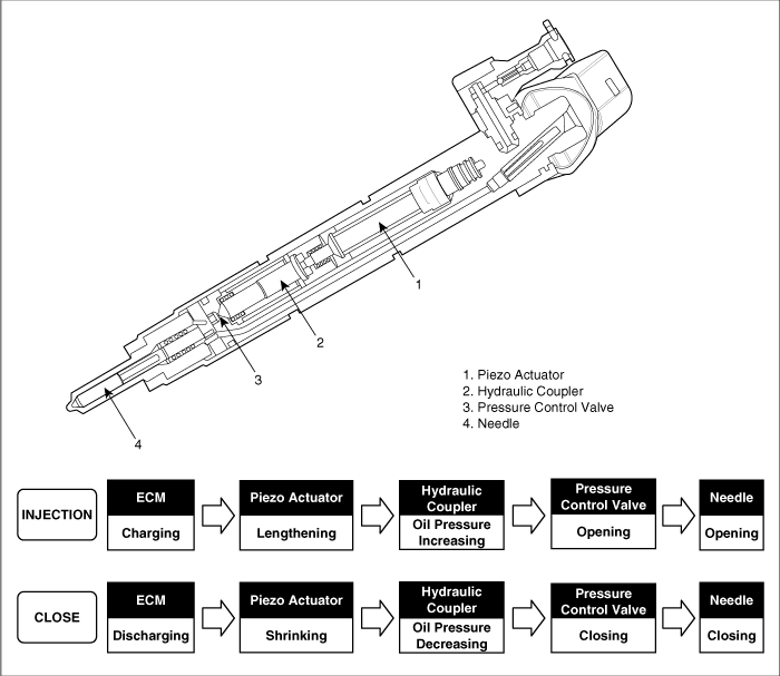
The injectors are installed on the cylinder head and inject the compressed fuel stored in common rail into each cylinder by ECM control signal. This consists of the piezo actuator, the hydraulic coupler which amplifies output of the piezo actuator, the pressure control valve which moves the needle, the needle which opens or closes the injection hole of the injector, the fuel inlet nipple, and the fuel return nipple.

1. Injector 2. Connector 3. Clamp | 4. Clamp Mounting Bolt 5. Injector Specific Data (7 digits) |

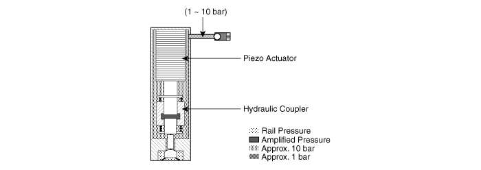
The Piezo Actuator is made up of several floors of cylindrical piezo-ceramic (height: approximately 90㎛). This lengthens by from 1.5% through 2.0% of its length if voltage is applied (Piezoelectric Converse Effect) and this length is “Stroke”. The number and the cross section of the ceramic are proportional to the actuator’s stroke and output respectively.
The hydraulic coupler is located under the piezo actuator and amplifies the actuator’s output by the cross section ratio of the upper and the lower pistons. At this time, the actuator’s stroke is lengthened. The hydraulic oil is the fuel and the oil pressure to operate the hydraulic coupler normally is from 1 through 10 bar.

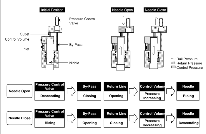
The Pressure Control Valve is located under the hydraulic coupler and controls the needle by amplified actuator's output.

The needle is located under the pressure control valve and finally opens or closes the injection hole.