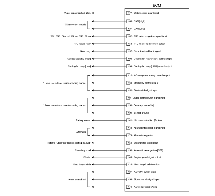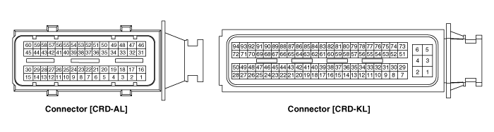
Pin | Description | Connected to |
1 | Injector (Cylinder #3) [High] control output | Injector (Cylinder #3) [With Immobilizer] |
Injector (Cylinder #2) [High] control output | Injector (Cylinder #2) [Without Immobilizer] | |
2 | Injector (Cylinder #2) [High] control output | Injector (Cylinder #2) [With Immobilizer] |
Injector (Cylinder #3) [High] control output | Injector (Cylinder #3) [Without Immobilizer] | |
3 | - |
|
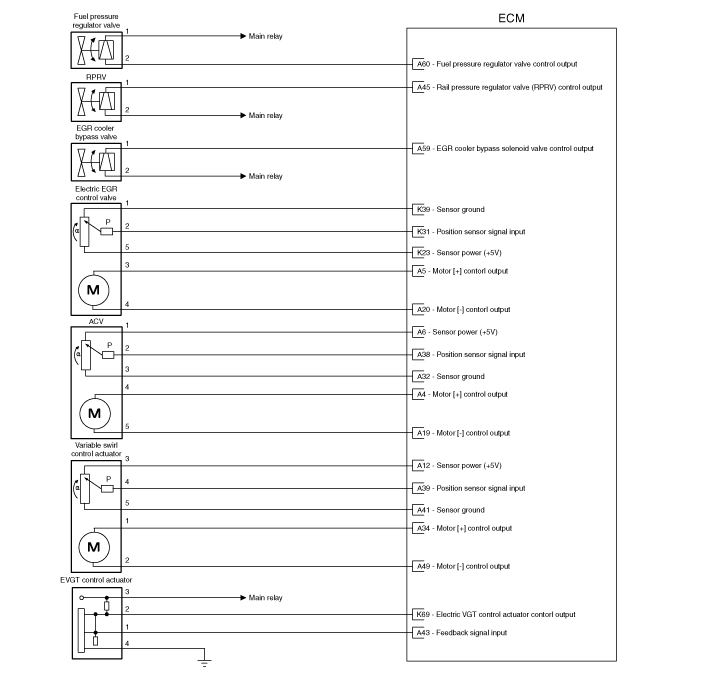
4 | Motor [+] control output | Air Control Valve (ACV) |
5 | Motor [+] control output | Electric EGR Control Valve (EEGR) |
6 | Sensor power (+5V) | Position Sensor in Air Control Valve (ACV) |
7 | Sensor power (+5V) | Boost Pressure Sensor (BPS) |
8 | - |
|
9 | - |
|
10 | Sensor power (+5V) | Rail Pressure Sensor (RPS) |
11 | - |
|
12 | Sensor power (+5V) | Position Sensor in Variable Swirl Control Actuator |
13 | Crankshaft Position Sensor (CKPS) signal input | Crankshaft Position Sensor (CKPS) |
14 | - |
|
15 | - |
|
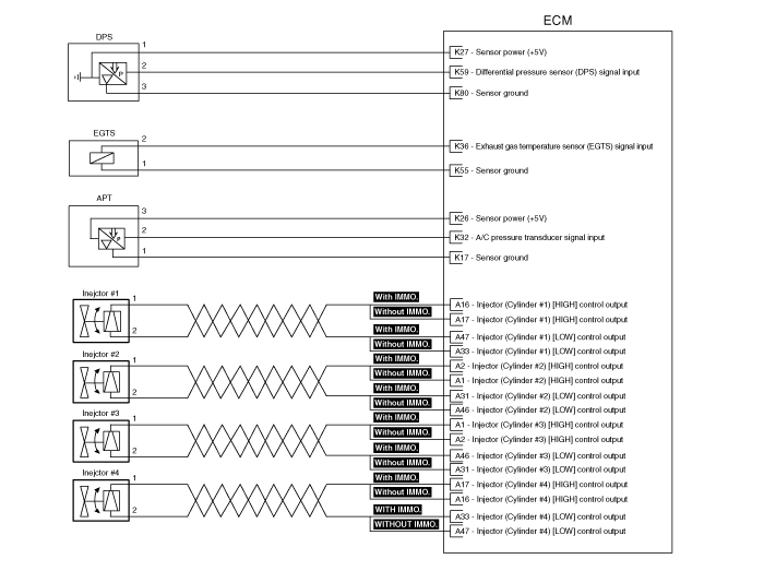
16 | Injector (Cylinder #1) [High] control output | Injector (Cylinder #1) [With Immobilizer] |
Injector (Cylinder #4) [High] control output | Injector (Cylinder #4) [Without Immobilizer] | |
17 | Injector (Cylinder #4) [High] control output | Injector (Cylinder #4) [With Immobilizer] |
Injector (Cylinder #1) [High] control output | Injector (Cylinder #1) [Without Immobilizer] | |
18 | - |
|
19 | Motor [-] control output | Air Control Valve (ACV) |
20 | Motor [-] control output | Electric EGR Control Valve (EEGR) |
21 | - |
|
22 | A/C Compressor Relay control output | A/C Compressor Relay |
23 | - |
|
24 | - |
|
25 | - |
|
26 | - |
|
27 | - |
|
28 | Sensor ground | Boost Pressure Sensor (BPS) |
29 | - |
|
30 | - |
|
31 | Injector (Cylinder #2) [Low] control output | Injector (Cylinder #2) [With Immobilizer] |
Injector (Cylinder #3) [Low] control output | Injector (Cylinder #3) [Without Immobilizer] | |
32 | Sensor ground | Position Sensor in Air Control Valve (ACV) |
33 | Injector (Cylinder #4) [Low] control output | Injector (Cylinder #4) [With Immobilizer] |
Injector (Cylinder #1) [Low] control output | Injector (Cylinder #1) [Without Immobilizer] | |
34 | Motor [+] control output | Variable Swirl Control Actuator |
35 | Sensor ground | Camshaft Position Sensor (CMPS) |
36 | Exhaust Gas Temperature Sensor (EGTS) signal input | Exhaust Gas Temperature Sensor (EGTS) |
37 | Engine Coolant Temperature Sensor (ECTS) signal input | Engine Coolant Temperature Sensor (ECTS) |
38 | Feed back signal input | Position Sensor in Air Control Valve (ACV) |
39 | Feed back signal input | Position Sensor in Variable Swirl Control Actuator |
40 | Sensor ground | Rail Pressure Sensor (RPS) |
41 | Sensor ground | Position Sensor in Variable Swirl Control Actuator |
42 | Alternator feedback signal input | Alternator |
43 | Electric VGT Control Actuator feedback signal input | Electric VGT Control Actuator |
44 | - | |
45 | Rail Pressure Regulator Valve (RPRV) control output | Rail Pressure Regulator Valve (RPRV) |
46 | Injector (Cylinder #3) [Low] control output | Injector (Cylinder #3) [With Immobilizer] |
Injector (Cylinder #2) [Low] control output | Injector (Cylinder #2) [Without Immobilizer] | |
47 | Injector (Cylinder #1) [Low] control output | Injector (Cylinder #1) [With Immobilizer] |
Injector (Cylinder #4) [Low] control output | Injector (Cylinder #4) [Without Immobilizer] | |
48 | - |
|
49 | Motor [-] control output | Variable Swirl Control Actuator |
50 | Sensor ground | Engine Coolant Temperature Sensor (ECTS) |
51 | - |
|
52 | Rail Pressure Sensor (RPS) signal input | Rail Pressure Sensor (RPS) |
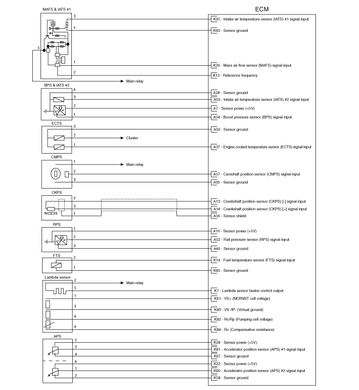
53 | Intake Air Temperature Sensor (IATS) #2 signal input | Intake Air Temperature Sensor (IATS) #2 [BPS] |
54 | Boost Pressure Sensor (BPS) signal input | Boost Pressure Sensor (BPS) |
55 | Sensor ground | Exhaust Gas Temperature Sensor (EGTS) |
56 | Sensor ground | Crankshaft Position Sensor (CKPS) |
57 | Camshaft Position Sensor (CMPS) signal input | Camshaft Position Sensor (CMPS) |
58 | PTC Heater Relay #1 control output | PTC Heater Relay #1 |
59 | EGR Cooler Bypass Solenoid Valve control output | EGR Cooler Bypass Solenoid Valve |
60 | Fuel Pressure Regulator Valve control output | Fuel Pressure Regulator Valve |
Pin | Description | Connected to |
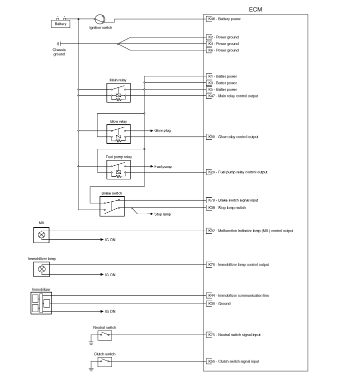
1 | Battery power | Main Relay |
2 | Power ground | Chassis Ground |
3 | Battery power | Main Relay |
4 | Power ground | Chassis Ground |
5 | Battery power | Main Relay |
6 | Power ground | Chassis Ground |
7 | Lambda Sensor Heater control output | Lambda Sensor |
8 | - |
|
9 | Cruise control switch signal input | Cruise control switch |
10 | Head lamp load detection | Head lamp switch |
11 | - |
|
12 | Reference frequency | Mass Air Flow Sensor (MAFS) |
13 | - |
|
14 | Fuel Temperature Sensor (FTS) signal input | Fuel Temperature Sensor (FTS) |
15 | - |
|
16 | - |
|
17 | Sensor ground | A/C Pressure Transducer (APT) |
18 | - |
|
19 | - | |
20 | Mass Air Flow Sensor (MAFS) signal input | Mass Air Flow Sensor (MAFS) |
21 | - | |
22 | Sensor power (+5V) | Accelerator Position Sensor (APS) #2 |
23 | Sensor power (+5V) | Position sensor in Electric EGR control valve (EEGR) |
24 | - |
|
25 | - |
|
26 | Sensor power (+5V) | A/C Pressure Transducer (APT) |
27 | Sensor power (+5V) | Differential Pressure Sensor (DPS) [With DPF] |
28 | Sensor power (+5V) | Accelerator Position Sensor (APS) #1 |
29 | Fuel Pump Relay control output | Fuel Pump Relay |
30 | Ground | Immobilizer Control Module |
31 | Feed back signal input | Position sensor in Electric EGR control valve |
32 | A/C Pressure Transducer (APT) signal input | A/C Pressure Transducer (APT) |
33 | - |
|
34 | - |
|
35 | Intake Air Temperature Sensor (IATS) #1 signal input | Intake Air Temperature Sensor (IATS) #1 [MAFS] |
36 | - |
|
37 | A/C "ON" switch signal | Heater control unit |
38 | Brake Main switch signal input | Brake Switch |
39 | Sensor ground | Position Sensor in Electric EGR Control Valve |
40 | ESP Auto recognition signal input | With ESP : Ground, Without ESP : Open |
41 | LIN communication (K-Line) | Battery Sensor |
42 | - | |
43 | Engine speed signal output | Cluster |
44 | Immobilizer communication line | Immobilizer Control Module |
45 | - |
|
46 | Battery power | Ignition Switch |
47 | Main Relay control output | Main Relay |
48 | - |
|
49 | - |
|
50 | Sensor power (+5V) | Cruise control switch |
51 | - | |
52 | Start Switch signal input |
|
53 | Wiper motor signal input | Multi-function switch |
54 | Blower switch signal input | Heater control unit |
55 | Clutch Switch signal input | Clutch Switch [M/T] |
56 | Automatic recognition [DPF] | Chassis Ground |
57 | Glow time feedback signal | Glow Relay |
58 | Sensor ground | Accelerator Position Sensor (APS) #2 |
59 | Differential Pressure Sensor (DPS) signal input | Differential Pressure Sensor (DPS) |
60 | Accelerator Position Sensor (APS) #2 signal input | Accelerator Position Sensor (APS) #2 |
61 | VS+ (NERNST Cell Voltage) | Lambda Sensor |
62 | Rc/Rp (Pumping Cell Voltage) | Lambda Sensor |
63 | Sensor ground | Mass Air Flow Sensor (MAFS) |
64 | - | |
65 | - |
|
66 | CAN 'A' [High] | Other Control Module |
67 | Sensor ground | Accelerator Position Sensor (APS) #1 |
68 | Start Relay control output |
|
69 | VGT Control Solenoid Valve control output | VGT Control Solenoid Valve |
70 | Immobilizer Lamp control output [With Immobilizer] | Immobilizer Lamp |
71 | - |
|
72 | - |
|
73 | Alternator Regulator | Alternator |
74 | A/C compressor switch | Heater control unit |
75 | Neutral Switch signal input | Neutral Switch [M/T] |
76 | Automatic recognition [2WD/4WD] | Chassis ground |
77 | Water Sensor signal input | Water Sensor [Fuel filter] |
78 | Brake Switch signal input | Brake Switch |
79 | - |
|
80 | Sensor ground | Differential Pressure Sensor (DPS) |
81 | Accelerator Position Sensor (APS) #1 signal input | Accelerator Position Sensor (APS) #1 |
82 | - |
|
83 | VS-/IP- (Virtual Ground) | Lambda Sensor |
84 | Rc (Compensative Resistance) | Lambda Sensor |
85 | Sensor ground | Fuel Temperature Sensor (FTS) |
86 | - | |
87 | CAN 'A' [Low] | Other Control Module |
88 | - |
|
89 | Sensor ground | Cruise control switch |
90 | Glow Relay control output | Glow Relay |
91 | - | |
92 | Malfunction Indicator Lamp (MIL) control output | Malfunction Indicator Lamp (MIL) |
93 | Cooling Fan Relay [High] control output | Cooling Fan Relay [High] |
94 | Cooling Fan Relay [Low] control output | Cooling Fan Relay [Low] |
Pin | Description | Condition | Type | Level | Test Result |
1 | Injector (Cylinder #3) [High] control output | Idle | Pulse | Battery Voltage ~ 80V | 45V |
Injector (Cylinder #2) [High] control output | 14.1Hz | ||||
2 | Injector (Cylinder #2) [High] control output | Idle | Pulse | Battery Voltage ~ 80V | 45V |
Injector (Cylinder #3) [High] control output | 14.1Hz | ||||
3 | - |
|
|
|
|
4 | Motor [+] control output | When ACV controlling | Pulse | High :Battery voltage |
|
Low :Max. 1.0V |
| ||||
5 | Motor [+] control output | When EEGR controlling | Pulse | High :Battery voltage |
|
Low :Max. 1.0V |
| ||||
6 | Sensor power (+5V) | IG Off | DC | Max. 0.5V | 23mV |
IG On | 4.9 ~ 5.1V | 4.91V | |||
7 | Sensor power (+5V) | IG OFF | DC | Max. 0.5V | 23mV |
IG ON | 4.9 ~ 5.1V | 4.95V | |||
8 | - |
|
|
|
|
9 | - |
|
|
|
|
10 | Sensor power (+5V) | IG OFF | DC | Max. 0.5V | 15mV |
IG ON | 4.9 ~ 5.1V | 4.91V | |||
11 | - |
|
|
|
|
12 | Sensor power (+5V) | IG OFF | DC | Max. 0.5V | 16mV |
IG ON | 4.9 ~ 5.1V | 4.91V | |||
13 | Crankshaft Position Sensor (CKPS) signal input | Idle | Pulse | High :Vcc or Battery voltage |
|
Low :Max. 0.5V |
| ||||
14 | - |
|
|
|
|
15 | - |
|
|
|
|
16 | Injector (Cylinder #1) [High] control output [With Immobilizer] | Idle | Pulse | Battery Voltage ~ 80V | 46.4V |
Injector (Cylinder #4) [High] control output [Without Immobilizer] | 7.418Hz | ||||
17 | Injector (Cylinder #4) [High] control output [With Immobilizer] | Idle | Pulse | Battery Voltage ~ 80V | 46.4V |
Injector (Cylinder #1) [High] control output [Without Immobilizer] | 7.418Hz | ||||
18 | - |
|
|
|
|
19 | Motor [-] control output | When ACV controlling | Pulse | High :Battery voltage |
|
Low :Max. 1.0V |
| ||||
20 | Motor [-] control output | When EEGR controlling | Pulse | High :Battery voltage |
|
Low :Max. 1.0V |
| ||||
21 | - |
|
|
|
|
22 | A/C Compressor Relay control output | A/C OFF | DC | Battery Voltage | 13.9V |
A/C ON | Max. 1.0V | 60mV | |||
23 | - |
|
|
|
|
24 | - |
|
|
|
|
25 | - |
|
|
|
|
26 | - |
|
|
|
|
27 | - |
|
|
|
|
28 | Sensor ground | Always | DC | Max. 50mV | -100mV |
29 | - |
|
|
|
|
30 | - |
|
|
|
|
31 | Injector (Cylinder #2) [Low] control output [With Immobilizer] | Idle | Pulse | High : Battery Voltage | 11.2V |
Low : Max. 1.0V | 200mV | ||||
Injector (Cylinder #3) [Low] control output [Without Immobilizer] | Peak Current : Max. 80V | 51.8V | |||
32 | Sensor ground | Idle | DC | Max. 50mV | -1.7mV |
33 | Injector (Cylinder #4) [Low] control output [With Immobilizer] | Idle | Pulse | High : Battery Voltage | 11.2V |
Low : Max. 1.0V | 200mV | ||||
Injector (Cylinder #1) [Low] control output [Without Immobilizer] | Peak Current : Max. 80V | 51.8V | |||
34 | Motor [+] control output | When VSA controlling | Pulse | High :Battery voltage |
|
Low :Max. 1.0V |
| ||||
35 | Sensor ground | Idle | DC | Max. 50 mV | 30mV |
36 | Exhaust Gas Temperature Sensor (EGTS) signal input | Idle | Analog | 0.5 ~ 4.5V | 910mV |
37 | Engine Coolant Temperature Sensor (ECTS) signal input | Idle | Analog | 0.5 ~ 4.5V | 910mV |
38 | Feedback signal input | Idle | DC | 0.17~4.83V | 255mV |
39 | Feedback sensor ground | Idle | DC | Max. 50 mV | 255mV |
40 | Sensor ground | Idle | DC | Max. 50mV | 13.2mV |
41 | Sensor ground | Idle | DC | Max. 50mV | 12mV |
42 | Alternator feedback signal | Idle | Pulse | High :Battery voltage |
|
Low :Max. 1.0V |
| ||||
43 | Feedback signal input | Idle | Pulse | High :Vcc or Battery voltage |
|
Low :Max. 1.0V |
| ||||
44 | - |
|
|
|
|
45 | Rail Pressure Regulator Valve (FPRV) control output | Idle | Pulse | High :Battery voltage |
|
Low :Max. 1.0V |
| ||||
Frequency =0.7~1.1kHz |
| ||||
46 | Injector (Cylinder #3) [Low] control output [With Immobilizer] | Idle | Pulse | High : Battery Voltage | 11.2V |
Low : Max. 1.0V | 200mV | ||||
Injector (Cylinder #2) [Low] control output [Without Immobilizer] | Peak Current : Max. 80V | 51.8V | |||
47 | Injector (Cylinder #1) [Low] control output [With Immobilizer] | Idle | Pulse | High : Battery Voltage | 11.2V |
Low : Max. 1.0V | 200mV | ||||
Injector (Cylinder #4) [Low] control output [Without Immobilizer] | Peak Current : Max. 80V | 51.8V | |||
48 | - |
|
|
|
|
49 | Motor [-] control output | When VSA controlling | Pulse | High :Battery voltage |
|
Low :Max. 1.0V |
| ||||
50 | Sensor ground | Always | DC | Max. 50mV | -3.301mV |
51 |
|
|
|
|
|
52 | Rail Pressure Sensor (RPS) signal input | IG ON | Analog | Max. 1.0V |
|
Idle | 1.0 ~ 1.5 V |
| |||
3000 RPM | 1.5 ~ 3.0 V |
| |||
53 | Intake Air Temperature Sensor (IATS) #2 signal input | Idle | Analog | 0.5 ~ 4.5V | 2.7V |
54 | Boost Pressure Sensor (BPS) signal input | IG ON | Analog | 0.5 ~ 4.5V | 1.59mV |
55 | Sensor ground | Idle | DC | Max. 50mV | 12mV |
56 | Sensor shield | Idle | DC | Max. 50mV | 31mV |
57 | Camshaft Position Sensor (CMPS) signal input | Idle | Pulse | High : Vcc or Battery Voltage | 4.76V |
Low : Max. 1.0V | -200mV | ||||
58 | PTC Heater Relay #1 control output | Relay Off | DC | Battery voltage |
|
Relay On | Max. 1.0V |
| |||
59 | EGR Cooler Bypass Solenoid Valve control output | Idle | Pulse | Battery voltage |
|
Max. 1.0V |
| ||||
60 | Fuel Pressure Regulator Valve control output | Idle | Pulse | High : Battery Voltage | 14.2V |
Low : Max. 1.0V | -234mV |
Pin | Description | Vehicle State | Type | Level | Test Result |
1 | Battery power | IG OFF | DC | Max. 1.0 V | 175mV |
IG ON | Battery Voltage | 12.77V | |||
2 | Power ground | Idle | DC | Max. 50mV |
|
3 | Battery power | IG OFF | DC | Max. 1.0 V | -25mV |
IG ON | Battery Voltage | 12.57V | |||
4 | Power ground | Idle | DC | Max. 50mV |
|
5 | Battery power | IG OFF | DC | Max. 1.0 V | 231mV |
IG ON | Battery Voltage | 12.57V | |||
6 | Power ground | Idle | DC | Max. 50mV |
|
7 | Lambda Sensor Heater control output | Vehicle Run | Pulse | High: Battery Voltage | 14.3V |
Low: Max. 1.0V | 220mV | ||||
8 | - |
|
|
|
|
9 | Cruise control switch signal | All Release | DC voltage | 5.0 ± 0.1 V |
|
Main SW | 5.0 ± 0.1 V |
| |||
Set SW | 0.5 ± 0.2 V |
| |||
Resume SW | 1.5 ± 0.2 V |
| |||
Cancel SW | 0 ± 0.2 V |
| |||
10 | Head lamp load detection |
|
|
|
|
11 | - |
|
|
|
|
12 | Reference frequency | Idle | Pulse | High : Vcc or Battery Voltage | 4.94V |
Low : Max. 1.0V | 340mV | ||||
13 | - |
|
|
|
|
14 | Fuel Temperature Sensor (FTS) signal input | Idle | Analog | 0.5 ~ 4.5V | 2.311V |
15 | - |
|
|
|
|
16 | - |
|
|
|
|
17 | Sensor ground | Idle | DC | Max. 50mV | -3.38mV |
18 | - |
|
|
|
|
19 | - | ||||
20 | Mass Air Flow Sensor (MAFS) signal input | Idle | Pulse | High : Vcc | 4.95V |
Low : Max. 1.0V | 350mV | ||||
21 | - |
| |||
22 | Sensor power (+5V) | IG OFF | DC | Max. 0.5V | -10mV |
IG ON | 4.9 ~ 5.1V | 4.99V | |||
23 | Sensor power (+5V) |
|
|
|
|
24 | - |
|
|
|
|
25 | - |
|
|
|
|
26 | Sensor power (+5V) | IG OFF | DC | Max. 0.5V | -50mV |
IG ON | 4.9 ~ 5.1V | 4.91V | |||
27 | Sensor power (+5V) | IG OFF | DC | Max. 0.5V | -10mV |
IG ON | 4.9 ~ 5.1V | 4.99V | |||
28 | Sensor power (+5V) | IG OFF | DC | Max. 0.5V | -10mV |
IG ON | 4.9 ~ 5.1V | 4.99V | |||
29 | Fuel Pump Relay control output | Relay Off | DC voltage | Battery voltage |
|
Relay On | Max. 1.0V |
| |||
30 | Ground | Always | DC | Max. 50mV | -3.8mV |
31 | Feedback signal input | Idle | DC | 0.17~4.83V |
|
32 | A/C Pressure Transducer (APT) signal input | A/C OFF | DC | Max. 4.8V | 1.76V |
A/C ON | Max. 50mV | 12mV | |||
33 | - |
|
|
|
|
34 | - |
|
|
|
|
35 | Intake Air Temperature Sensor (IATS) #1 signal input | Idle | Analog | 0.2 ~ 4.8V | 1.48V |
36 | - |
|
|
|
|
37 | A/C "ON" switch signal |
|
|
|
|
38 | Brake Main switch signal input | Release | DC | Max. 0.5V | -47mV |
Push | Battery Voltage | 13.57V | |||
39 | Feedback sensor ground | Idle | DC | Max. 50 mV |
|
40 | ESP Auto recognition signal input | ESP/TCS | DC | Max. 0.5V |
|
ABS | Battery voltage |
| |||
41 | LIN Communication (K-Line) | When communicating after IG ON | Pulse | HIGH : Min. Vb*0.8 |
|
LOW : Max Vb*0.2 |
| ||||
42 | - |
|
|
|
|
43 | Engine speed signal output |
|
|
|
|
44 | Immobilizer communication line | When communicating after IG ON | Pulse | High: Min. 8.5V | 10.8V |
Low: Max. 3.5V | 1.1V | ||||
45 | - |
|
|
|
|
46 | Battery power | IG OFF | DC | Max. 1.0V | 18mV |
IG ON | Battery Voltage | 12.57V | |||
47 | Main Relay control output | Relay OFF | DC | Battery Voltage | 12.94V |
Relay ON | Max. 1.0V | 740mV | |||
48 | - |
|
|
|
|
49 | - |
|
|
|
|
50 | Sensor power (+5V) | IG OFF | DC | Max. 0.5V | 15mV |
IG ON | 4.9 ~ 5.1V | 4.91V | |||
51 | - |
|
|
|
|
52 | Start Switch signal input | Cranking | Pulse | High : Vcc | 11.02V |
Low : Max. 0.5V | 68mV | ||||
53 | Wiper Motor signal input |
|
|
|
|
54 | Blower switch signal input |
|
|
|
|
55 | Clutch Switch signal input | Push | DC | Max. 0.5V | -20mV |
Release | Battery Voltage | 13.74V | |||
56 | DPF auto recognition | Non-DPF | DC voltage | Battery voltage |
|
DPF | Max. 0.5V |
| |||
57 | Glow time Feedback signal input | Normal | DC voltage | Battery voltage |
|
Error | Max. 2.0V |
| |||
58 | Sensor ground | Idle | DC | Max. 50mV | -3.145mV |
59 | Differential Pressure Sensor (DPS) signal input | Idle | Analog | 0.5 ~ 4.5V | 1.039V (Idle) |
1.319V (acceleration) | |||||
60 | Accelerator Position Sensor (APS) #2 signal input | C.T | Analog | 0.3 ~ 0.9V | 0.39mV |
W.O.T | 1.5 ~ 3.0V | 2.14V | |||
61 | VS+ (NERNST Cell Voltage) | Engine | Analog | Normal: 450±50mV | 2.94V |
Running | Rich: Max. Normal +150mV | ||||
| Lean: Min. Normal -150mV | ||||
62 | Rc/Rp (Pumping Cell Voltage) | Engine | Analog | Normal: 0±500mV | 2.84V |
Running | Rich: Min. Normal -1.5mV | ||||
| Lean: Max. Normal +1.5mV | ||||
63 | Sensor ground | Idle | DC | Max. 50mV | 2.1mV |
64 | - |
| |||
65 | - |
|
|
|
|
66 | CAN [High] | RECESSIVE | Pulse | 2.0 ~ 3.0V |
|
DOMINANT | 2.75 ∼ 4.5V |
| |||
67 | Sensor ground | Idle | DC | Max. 50mV | 3.8mV |
68 | Start Relay control output | Relay OFF | DC | Battery Voltage | 12.94V |
Relay ON | Max. 1.0V | 300mV | |||
69 | Electric VGT Control Actuator PWM signal input | Idle | Pulse | HI : Battery voltage |
|
LO : Max. 0.5V |
| ||||
70 | Immobilizer Lamp control output [With Immobilizer] | Lamp OFF | DC | Battery Voltage | 12.54V |
Lamp ON | Max. 1.0V | 65mV | |||
71 | - |
|
|
|
|
72 | - |
|
|
|
|
73 | Alternator Rgulator | Idle | Pulse | HI : Min. 4.0V |
|
LO : Max. 1.0V |
| ||||
74 | A/C compressor switch |
|
|
|
|
75 | Neutral Switch signal input | Switch OFF | DC | Battery Voltage | 12.54V |
(1st) | |||||
Switch ON | Max. 0.5V | -20mV | |||
(Neutral) | |||||
76 | Automatic recognition [2WD/4WD] | 2WD | DC voltage | Battery voltage |
|
4WD | Max. 0.5V |
| |||
77 | Water Sensor signal input | Full of water | Analog | Battery Voltage | 11.26V |
No water | Max. 1V | -20mV | |||
78 | Brake Switch signal input | Release | DC | Battery Voltage | 14.14V |
Push | Max. 0.5V | -20mV | |||
79 | - |
|
|
|
|
80 | Sensor ground | Idle | DC | Max. 50mV | 12mV |
81 | Accelerator Position Sensor (APS) #1 signal input | C.T | Analog | 0.3 ~ 0.9V | 682.8mV |
W.O.T | 4.0 ~ 4.8V | 4.029V | |||
82 | - |
|
|
|
|
83 | VS-/IP- (Virtual Ground) | Engine | Analog | 2.4 ~ 2.6V | 2.462V |
Running | |||||
84 | Rc (Compensative Resistance) | Engine | Analog | |Current Pump - Current Adjust| < 0.2V | 2.83mV |
Running | |||||
85 | Sensor ground | Idle | DC | Max. 50mV | 3mV |
86 | - |
|
|
|
|
87 | CAN 'A' [Low] | RECESSIVE | Pulse | 2.0 ~ 3.0V | 2.57V |
DOMINANT | 0.5 ∼ 2.25V | 1.62V | |||
88 | - |
|
|
|
|
89 | Sensor ground | Idle | DC | Max. 50mV | 16mV |
90 | Glow Relay control output | Relay OFF | DC | Battery Voltage | 12.46V |
Relay ON | Max. 1.0V | 60mV | |||
91 | - |
|
|
|
|
92 | Malfunction Indicator Lamp (MIL) control output | Lamp OFF | DC | Battery Voltage | 12.3V |
Lamp ON | Max. 1.0V | 80mV | |||
93 | Cooling Fan Relay [High] control output | Relay OFF | DC | Battery Voltage | 12.3V |
Relay ON | Max. 1.0V | 121mV | |||
94 | Cooling Fan Relay [Low] control output | Relay OFF | DC | Battery Voltage | 14.1V |
Relay ON | Max. 1.0V | 215mV |