
The Electronic Throttle Control(ETC) system is made of the components throttle body, Throttle Position Sensor(TPS) 1&2 and Accelerator Position Sensor(APS) 1&2. The APS is mounted in the accelerator pedal to detect the opening angle of the accelerator pedal. It has 2 sensors to detect the accelerator position and a malfunction of the accelerator position sensor. The ECM judges the current opening angle of the accelerator pedal from APS1&2, and the ECM controls the throttle motor based on these signals.
Checking output signals from APS 1 under detecting condition, if output signals are below the threshold, ECM sets P2122.
Item | Detecting Condition | Possible Cause |
DTC Strategy |
•
This code detects a continuous short to ground or open in either the circuit or the sensor (0-100%) |
•
Poor connection
•
Open or short to ground in power circuit
•
Open or short to ground in signal circuit
•
Faulty APS
•
Faulty ECM |
Enable Conditions |
•
Ignition "ON" | |
Threshold value |
•
APS1 < 0.125V | |
Diagnosis Time |
•
Continuous | |
MIL On Condition |
•
1 Driving Cycle |
Pedal Position | Output Voltage(V) [Vref = 5.0V] | |
APS1 | APS2 | |
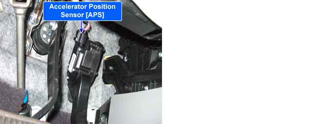
C.T | 0.7 ~ 0.8V | 0.29 ~ 0.46V |
W.O.T | 3.85 ~ 4.35V | 1.93 ~ 2.18V |
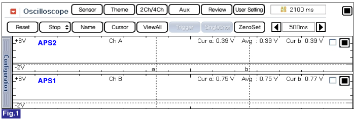
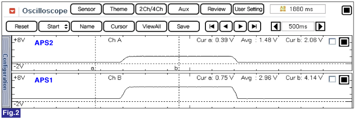
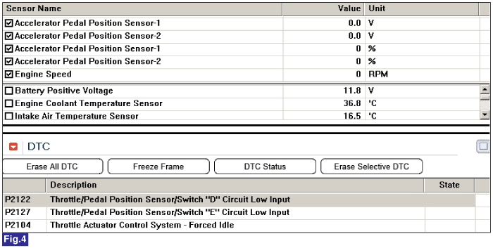
Fig.1) Normal waveform of APS1 & APS2 with no acceleration
Fig.2) Normal waveform of APS1 & APS2 with acceleration
Fig.3) Normal data of APS1 & APS2 at ig on.
Fig.4) Abormal data of APS1 & APS2 when APS1 & APS2 circuit open
Signal waveform of APS 1 & 2 shows that APS 2 increases voltage just half of APS 1 voltage increase when accelerating.