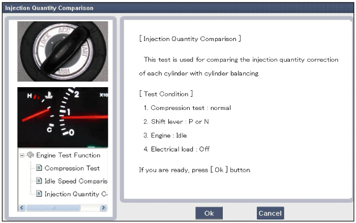
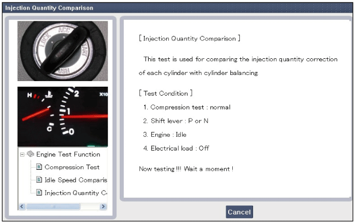
Disconnect the injector connector (A).
Common Rail Fuel Injection System operates with extremely high pressure [approximately 1,600 bar (160 MPa / 23,206 psi)], so never perform any work on injection system with engine running or within 30 seconds after the engine stops.
Keep cleanly the parts and the working area.
Pay attention to a foreign substance.
Just before installing injector, tube or hose, remove the protect-cap attached on them.
Do not remove injector except for special case.
When installing Injector
Wash the contact area of the injector and replace the washer (gasket) with a new one.
Spread oil on the injector O-ring.
To protect damage caused by shock, vertically insert the injector into the cylinder head.
When installing High Pressure Fuel Pipe
Do not use again the used high pressure fuel pipe.
Install the flange nut correctly.
Turn ignition switch OFF and disconnect the negative (-) battery cable.
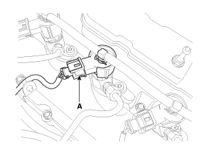
Disconnect the injector connector (A).

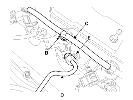
After removing the clip (B), disconnect the retun hose (C) from the injectors.
Disconnect the high pressure fuel pipe (D) connecting the injectors with the common rail.
Unscrew the clamp tightening bolt (E) and pull the injector upward.
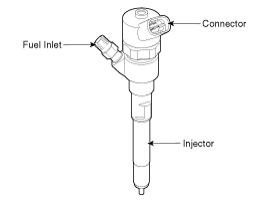
If the injector adheres to the cylinder head, use the special Service Tool (SST No. : 09351-4A300)
Installation is reverse of removal.
Before replacing or reinstalling the injector and the washer,make sure to remove carbon deposits from the injector holes using the hole cleaning tool [SST No.:09351-27300](to ensure sealability against exhaust gas).
If re-installing injectors after removing, clean the injector bodies and contact surfaces with washers as well as the injector holes. Once the injector have been removed, the mating copper washer (A) must be replaced with new one.
When installing the high pressure fuel pipe connecting the common rail and injector, follow the below procedure.
Temporarily install the nuts on common rail and injector
Install the injector side and common rail side sequentially
When installing the high pressure fuel pipe, apply the specified tightening torques with the special service tool (Refer to below table).
Item | Dimension | SST No. |
Flange Nut (Injector Side) | 14 mm (0.551 in) | 09314-27110 |
Flange Nut (Common Rail Side) | 17 mm (0.669 in) | 09314-27120 |
Injector clamp installation bolt:
29.4 ~ 33.4 N.m (3.0 ~ 3.4 kgf.m, 27.1 ~ 24.6 lb-ft)
High pressure fuel pipe installation nut:
24.5 ~ 28.4 N.m (2.5 ~ 2.9 kgf.m, 18.1 ~ 21.0 lb-ft)
Common Rail Fuel Injection System operates with extremely high pressure [approximately 1,600 bar (160 MPa / 23,206 psi)], so never perform any work on injection system with engine running or within 30 seconds after the engine stops.
Keep cleanly the parts and the working area.
Pay attention to a foreign substance.
Just before installing injector, tube or hose, remove the protect-cap attached on them.
Do not remove injector except for special case.
When installing Injector
- Wash the contact area of the injector and replace the washer (gasket) with a new one.
- Spread oil on the injector O-ring.
- To protect damage caused by shock, vertically insert the injector into the cylinder head.
When installing High Pressure Fuel Pipe
- Do not use again the used high pressure fuel pipe.
- Install the flange nut correctly.
After replacing injector, MUST input the injector specific data (7 digits) of each cylinder into ECM with the GDS.
Remove the injector (Refer to "Removal" procedure).
Install the injector (Refer to "Installation" procedure).
Perform "Injector Specific Data Input" procedure (Refer to "Injector Specific Data Input" procedure).
After replacing injector, MUST input the injector specific data (7 digit) of each cylinder into ECM with the GDS.
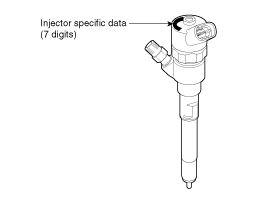
Turn ignition switch OFF.
Connect the GDS to Data Link Connector (DLC).
Turn ignition switch ON.
Select "Vehicle, Model year, Engine, System".
Select "Vehicle S/W Management".
Select "injector Specific Data".
Perform the procedure in accordance with the message.
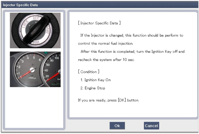
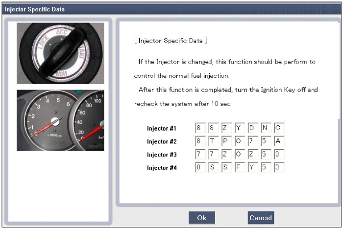
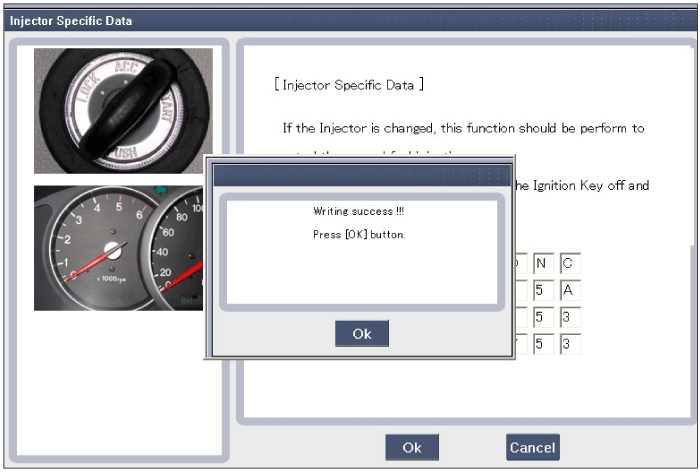
After selecting "OK" on the "Writing success" message, turn ignition switch OFF.
In about 10 seconds, turn ignition switch ON and recheck the injector specific data memorized in the ECM.
In case of failure, input the injector specific data (7 digits) into ECM again.
Turn ignition switch OFF.
Connect the GDS to Data Link Connector (DLC).
Turn ignition switch ON.
Select "Vehicle, Model year, Engine, System".
Select "Vehicle S/W Management".
Select "Engine Test Function".
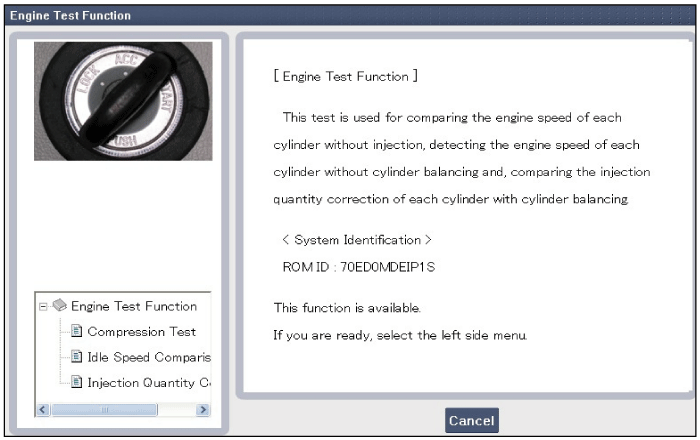
Select "Compression Test".
Perform the test in accordance with the message.
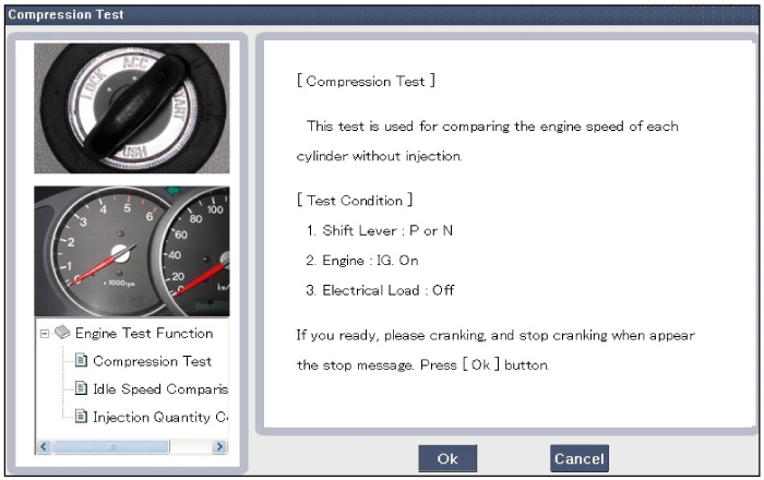
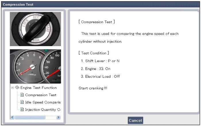
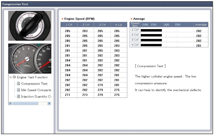
If a cylinder's engine speed is higher than the other cylinders, the cylinder's compression pressure is low.
Turn ignition switch OFF.
Connect the GDS to Data Link Connector (DLC).
Turn ignition switch ON.
Select "Vehicle, Model year, Engine, System".
Select "Vehicle S/W Management".
Select "Engine Test Function".

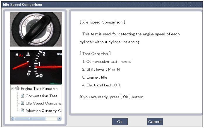
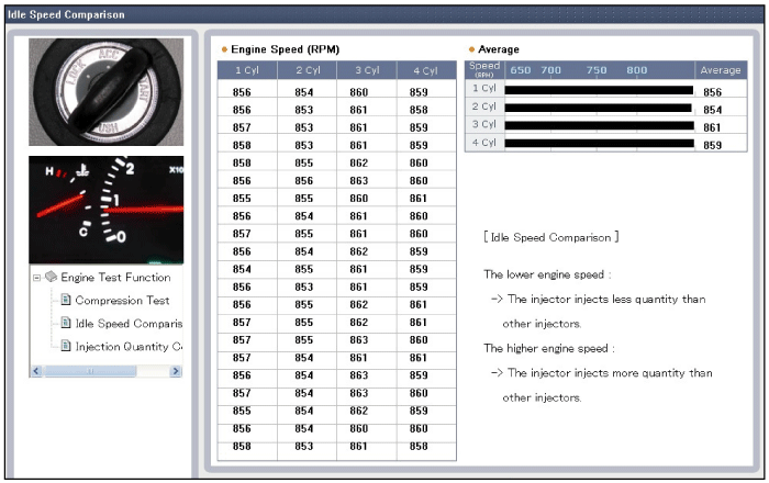
Select "Idle Speed Comparision".
Perform the test in accordance with the message.
Turn ignition switch OFF.
Connect the GDS to Data Link Connector (DLC).
Turn ignition switch ON.
Select "Vehicle, Model year, Engine, System".
Select "Vehicle S/W Management".
Select "Engine Test Function".

Select "Injection Quantity Comparison".
Perform the test in accordance with the message.
