4.
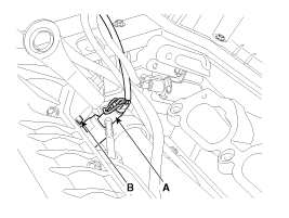
Remove the installation bolt (B), and then remove the valve from the engine.
[Bank 1]
[Bank 2]
Turn the ignition switch OFF.
Disconnect the OCV connector.
Measure resistance between the OCV terminals 1 and 2.
Check that the resistance is within the specification.
Specification: Refer to “Specification”
Turn the ignition switch OFF and disconnect the battery negative (-) cable.
Remove the intake manifold (Refer to “Intake And Exhaust System” in EM group).
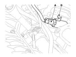
Disconnect the CVVT oil control valve connector (A).
Remove the installation bolt (B), and then remove the valve from the engine.
[Bank 1]
[Bank 2]
Turn the ignition switch OFF and disconnect the battery negative (-) cable.
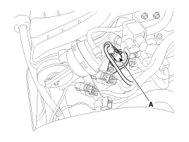
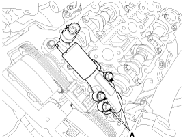
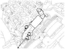
Disconnect the CVVT oil control valve connector (A).
[Bank 1]
[Bank 2]
Remove the cylinder head cover (Refer to “Cylinder Head Assembly” in EM group).
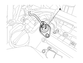
Remove the installation bolt (A), and then remove the valve from the engine.
[Bank 1]
[Bank 2]
Install the component with the specified torques.
Note that i
nternal damage may occur when the component is dropped. In this case, use it after inspecting.
Apply the engine oil to the valve O-ring.
Exactly distinguish the color of the valve and harness connectors in bank 1 and 2 when installing, or the engine will operate abnormally (Refer to the table below).
Items | Component Side | Harness Side |
Bank 1 (RH) | Grey | |
Bank 2 (LH) | Black | |
Installation is reverse of removal.
CVVT oil control valve installation bolt:
9.8 ~ 11.8 N.m (1.0 ~ 1.2 kgf.m, 7.2 ~ 8.7 lb-ft)
