Thoroughly check connectors for looseness, poor connection, bending, corrosion, contamination, deterioration, or damage.
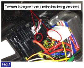
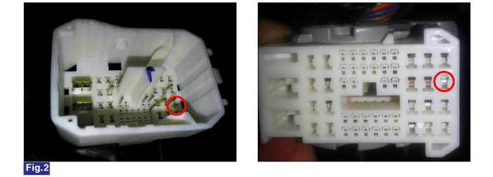
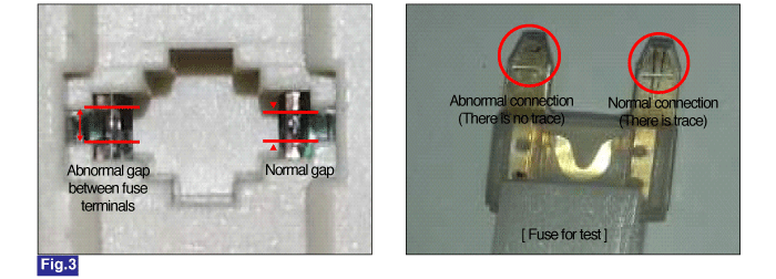
Fig.1) Poor connection
Fig.2) Pulled terminal
Fig.3) Poor connect of fuse (check the trace after clamping test fuse)
Many malfunctions in the electrical system are caused by poor harness and terminals. Faults can also be caused by interference from other electrical systems, and mechanical or chemical damage.
Thoroughly check connectors for looseness, poor connection, bending, corrosion, contamination, deterioration, or damage.


Fig.1) Poor connection
Fig.2) Pulled terminal
Fig.3) Poor connect of fuse (check the trace after clamping test fuse)
Has a problem been found ?
 | ▶ Repair as necessary and then go to "Verification of Vehicle Repair" procedure. |
 | ▶ Go to next step. |
IG "OFF".
Connect probes to corresponding terminals in brake circuit by referring to below figure.
Connect GDS to DLC connector.
IG "ON".
Measure voltage between each terminal in brake circuit and chassis ground.
Check "brake light switch" and "pressure sensor" parameters in "Current Data" menu on GDS.
※ Press/release the brake pedal and accelerating/decelerating the vehicle several times to check intermittent problem.
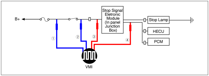
Item | Possible Cause | ① Power stage of stop lamp switch | ② Output stage of stop lamp switch | ③ Input stage of stop signal eletronic module | ④ Output stage of stop signal eletronic module |
- | Normal (Stop Lamp ON/GDS input signal OK) | B+ | B+ ↔ 0V | B+ ↔ 0V | B+ ↔ 0V |
A | Open in internal circuit of stop lamp switch/Poor connection | B+ | 0V | 0V | 0V |
B | Internal short in stop lamp switch | B+ | B+ | B+ | B+ |
C | Open in internal circuit of stop signal eletronic module | B+ | B+ ↔ 0V | B+ ↔ 0V | 0V |
D | Internal short in stop signal eletronic module | B+ | B+ ↔ 0V | B+ ↔ 0V | Stuck at B+ or 0V |
E | Open in power circuit | 0V | 0V | 0V | 0V |
F | Short in power circuit | B+ | B+ ↔ 0V | B+ ↔ 0V | Intermittent switching error |
G | Poor connection bewteen output stage of stop lamp siwtch and input stage of stop signal eletronic module | B+ | B+ ↔ 0V | 0V | 0V |
H | Poor connection between output stage of stop signal eletronic module and stop lamp(stop lamp not illuminated) | B+ | B+ ↔ 0V | B+ ↔ 0V | B+ ↔ 0V |
I | Poor connection between output stage of stop signal eletronic module and HECU(GDS'data not changed) | B+ | B+ ↔ 0V | B+ ↔ 0V | B+ ↔ 0V |
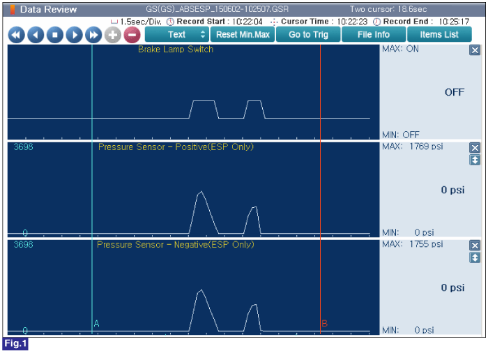
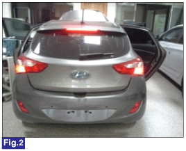
Fig.1) Pressure Sensor's data is increased with brake switch turning ON when the brake pedal is depressed. (normal)
Fig.2) Stop lamp turns ON with brake switch turning ON when the brake pedal is depressed. (normal)
Is the measured value within specifications?
 | ▶ Go to next procedure. |
 | A (Open in internal circuit of stop lamp switch/Poor connection) ▶ Recheck above brake circuit inspection after replace brake switch with a new one. |
B (Internal short in stop lamp switch) 1) Recheck above brake circuit inspection after remove brake switch. 2) Measure voltage between each terminal in brake circuit and chassis ground and compare the voltage with below table. |
① Power stage of stop lamp switch | ② Output stage of stop lamp switch | ③ Input stage of stop signal eletronic module | ④ Output stage of stop signal eletronic module |
B+ | 0V | 0V | 0V |
3) In case of the same voltage with above table, replace brake switch by referring to shop manual. 4) If the voltage at ②/③/④ is B+, it means short to battery in brake circuit. Repair short circuit and then, go to "Verification of vehicle Repair" procedure. C (Open in internal circuit of stop signal eletronic module) ▶ Recheck above brake circuit inspection after replace stop signal eletronic module with a new one. |
D (Internal short in stop signal eletronic module) 1) Recheck above brake circuit inspection after remove stop signal eletronic module. 2) Measure voltage between each terminal in brake circuit and chassis ground and compare the voltage with below table. |
① Power stage of stop lamp switch | ② Output stage of stop lamp switch | ③ Input stage of stop signal eletronic module | ④ Output stage of stop signal eletronic module |
B+ | B+ ↔ 0V | B+ ↔ 0V | 0V |
3) In case of the same voltage with above table, replace brake switch by referring to shop manual. 4) If the voltage at ④ is B+, it means short to battery in corresponding line. Repair short circuit and then, go to "Verification of vehicle Repair" procedure. E (Open in power circuit) ▶ Check connection state of stop lamp connector/stop lamp fuse state/open in power line. F (Short in power circuit) ▶ Check stop lamp fuse for being blown/short to ground in power line. G (Poor connection bewteen output stage of stop lamp siwtch and input stage of stop signal eletronic module) ▶ Check connection state of middle connector between stop lamp switch and stop signal eletronic module. ▶ If connection state is OK, repair open or short to ground in corresponding circuit and then, go to "Verification of vehicle Repair" procedure. H (Poor connection between output stage of stop signal eletronic module and stop lamp(stop lamp not illuminated)) ▶ Check connection state of stop lamp connector/stop lamp/middle connector between stop lamp and stop signal eletronic module/open or short in corresponding circuit. I (Poor connection between output stage of stop signal eletronic module and HECU(GDS'data not changed)) ▶ Check connection state of HECU connector/middle connector between HECU and stop signal eletronic module/open or short in corresponding circuit. |