4.
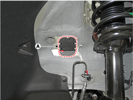
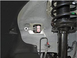
Disconnect the back-up lamp swtich connector (A) and vehicle speed sensor connector (B).
Remove the air cleaner assembly and air duct.
(Refer to Engine Mechanical System - "Air cleaner")
Remove the battery and battery tray.
(Refer to Engine Electrical System - "Battery")
Remove the ECM.
(Refer to Engine Control System - "ECM")
Disconnect the back-up lamp swtich connector (A) and vehicle speed sensor connector (B).
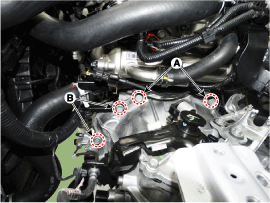
Disconnect the shift cable (A) and select cable (B) after removing the snap pin (C).
Remove the ground bolts (A).
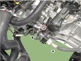
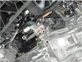
Disconnect the neutral switch connector (A).
Remove the clutch tube bracket bolt (B).
Remove the transaxle upper mounting bolts (A-2ea) and the starter motor mounting bolts (B-2ea).
Tightening torque :
(A) 58.8 ~ 78.5 N.m (6.0 ~ 8.0 kgf.m, 43.4 ~ 57.9 lb-ft)
(B) 49.0 ~ 63.7 N.m (5.0 ~ 6.5 kgf.m, 36.2 ~ 47.0 lb-ft)
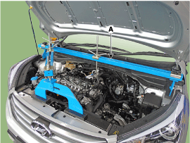
Assembled the engine support fixture. (beam No.: 09200-38001 or 09200-3N000, supporter No.: 09200-2S000)
(Refer to Special Service Tools - " Engine support fixture special tool assembly drawing")
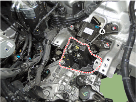
Using the engine support fixture (A), hold the engine and transaxle assembly safely.
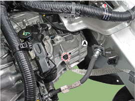
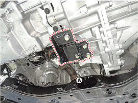
Remove the manual transaxle mounting bracket cover (A).
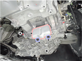
Remove the manual transaxle support bracket mounting bolts (A).
Tightening torque :
88.3 ~ 107.9 N.m (9.0 ~ 11.0 kgf.m, 65.1 ~ 79.6 lb-ft)
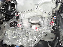
Remove the manual transaxle support bracket (A).
Tightening torque :
58.9 ~ 78.5 N.m (6.0 ~ 8.0 kgf.m, 43.4 ~ 57.8 lb-ft)
Remove the engine room under cover.
(Referto Engine Mechanical System - "Engine Room Under Cover")
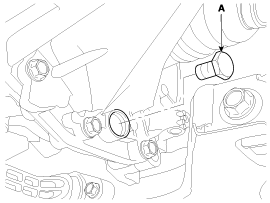
Drain the manual transaxle oil after loosening the drain plug (A) and then install the drain plug with new gasket.
Tightening torque :
58.9 ~ 78.5 N.m (6.0 ~ 8.0 kgf.m, 43.4 ~ 57.8 lb-ft)
Remove the drive shaft assembly.
(Refer to Driveshaft and axle - "Front Driveshaft")
Remove the clutch release cylinder assembly (A) by removing bolts (B-2ea).
Tightening torque :
14.7 ~ 21.6 N.m (1.5 ~ 2.2 kgf.m, 10.9 ~ 15.9 lb-ft)
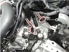
Loosen the intercooler pipe (A) by loosening a clamp and removing the bolts (B-2ea).
Tightening torque :
19.6 ~ 26.4 N.m (2.0 ~ 2.7 kgf.m, 14.4 ~ 19.5 lb-ft)
Remove the roll rod bracket (C) after revmoving the bolt (A-1ea, B-2ea).
Tightening torque :
(A) 107.9 ~ 127.5 N.m (11.0 ~ 13.0 kgf.m, 79.6 ~ 94.1 lb-ft)
(B) 49.0 ~ 63.7 N.m (5.0 ~ 6.5 kgf.m, 36.2 ~ 47.0 lb-ft)
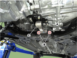
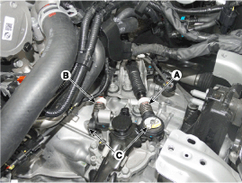
Remove the roll rod support bracket (A).
Tightening torque :
49.0 ~ 68.6 N.m (5.0 ~ 7.0 kgf.m, 36.2 ~ 50.6 lb-ft)
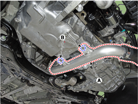
Remove the dust cover by removing the bolts (A-2ea).
Remove the mounting bolts(A-3ea, B-2ea) of lower part of the transaxle, and the left side cover and remove the transaxle assembly by supporting it with a jack.
Be careful not to damage other system or parts near by when removing the engine and transaxle assembly.
Tightening torque :
(A) 34.3 ~ 49.1 N.m (3.5 ~ 5.0 kgf.m, 25.3 ~ 36.2 lb-ft)
(B) 42.2 ~ 54.0 N.m (4.3 ~ 5.5 kgf.m, 31.1 ~ 39.8 lb-ft)
Install in the reverse order of removal.
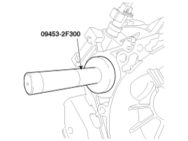
If the oil seal on the transaxle case side is damaged and fluid is leaking, replace the oil seal with a new unit. When installing the new oil seal, use the specialized tool (oil seal installer, 09453-2F300).
Adding manual transaxle fluid after Installing the manual transaxle.
(Refer to Manual Transaxle System - "Manual Transaxle Fluid")
