Check if current vehicle speed is same as vehicle speed displayed on the GDS.

Check the vehicle speed sensor by using the scan tool.
(if normal, current vehicle speed is display)
Check if current vehicle speed is same as vehicle speed displayed on the GDS.

Check the damage to the connectors and wiring.
Check the power.
Turn ignition switch OFF.
Disconnet the vehicle speed sensor.
Turn ignition switch ON.
Check the voltage of the power terminal.
Specification : 11.5V ~ 13.0V
Check the signal.
Turn ignition switch OFF.
Disconnet the vehicle speed sensor.
Turn ignition switch ON.
Check the voltage of the signal terminal.
Specification : 8.0V ~ 11.5V
Check the ground.
Turn ignition switch OFF.
Disconnet the vehicle speed sensor.
Turn ignition switch ON.
Check the voltage between signal terminal and body ground.
Check the voltage between signal terminal and ground terminal.
Specification : (4) - (5) = Within 200mV
IG KEY "OFF", ENGINE "OFF".
Disconnect the vehicle speed sensor connector.
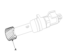
Disconnect the vehicle speed sensor and driven gear.
Check the wear of spline (A).

Check rotating state of vehicle speed sensor driven gear.
Connect the vehicle speed sensor connector and IG KEY "ON".
Rotate the driven gear with hand.
Specification : Vehicle Speed Signal generates.
Remove the air cleaner assembly.
(Refer to Engine Mechanical System - "Air Cleaner")
Remove the battery and battery tray.
(Refer to Engine Electrical System - "Battery")
Remove the ECM.
(Refer to Engine Control System - "ECM")
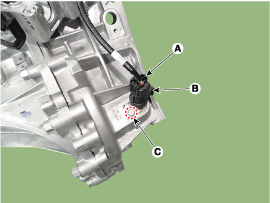
Disconnect the vehicle speed sensor (A).
Remove the vehicle speed sensor (B) after removing the mounting bolt (C).
Tightening torque:
4.9 ~ 6.9 N.m (0.5 ~ 0.7 kgf.m, 3.6 ~ 5.1 lb.ft)

Install in the reverse order of removal.
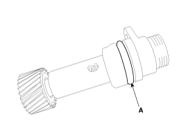
Do not reuse the O-ring (A).
