Stall speed too low in both "D" and "R" ranges
Malfunction of torque converter(D)
Insufficient engine output
When there is an abnormality in driving, follow the instruction below.
Connect the data link connector(DLC) to a scan tool(refer to the scan tool manual for details).
Turn or the ignition switch, power or the scan tool and choose '01.HYUNDAI VEHICLE DIAGNOSIS' on the 'INITIAL SCREEN'.
Select the vehicle model and system.
When the fault is detected, the relevant DTC will set.
If there is a fuel and emissions DTCs, first check the fuel and emission system as indicated by the DTC
Clear the DTC and data in the CLEAR MENU.
Drive the vehicle for seveual minites under the same conditions as those indicated by the data, and then recheck for a DTC.
If the A/T DTC returns, go to the DTC troubleshooting index. If the DTC does not return, there was an intermittent problem within the circuit. Make surt all pins and terminals in the circuit art tight.
Trouble symptom | Probable cause | |
Communication with HI-SCAN is not possible If communication with the HI-SCAN is not possible, the cause is probably a defective diagnosis line or the TCM is not functioning. | - Malfunction diagnosis line - Malfunction of connector - Malfunction of the TCM | |
Driving impossible | Starting impossible Starting is not possible when the selector lever is in P or N range. In such cases, the cause is probably a defective engine system, torque converter or oil pump. | - Malfunction of the engine system - Malfunction of the torque converter - Malfunction of the oil pump |
Does not move forward If the vehicle does not move forward when the selector lever is shifted from N to D, 3, 2 or L range while the engine is idling, the cause is probably abnormal line pressure or a malfunction of the underdrive clutch or valve body. | - Abnormal line pressure - Malfunction of the underdrive solenoid valve - Malfunction of the underdrive clutch - Malfunction of the valve body | |
Does not reverse If the vehicle does not reverse when the selector lever is shifted from N to R range while the engine is idling, the cause is probably abnormal pressure in the reverse clutch or low and reverse brake or a malfunction of the reverse clutch, low and reverse brake or valve body. | - Abnormal reverse clutch pressure - Abnormal low and reverse brake pressure - Malfunction of the low and reverse brake solenoid valve - Malfunction of the reverse clutch - Malfunction of the low and reverse brake - Malfunction of the valve body | |
Does not move (forward or reverse) If the vehicle does not move forward or reverse when the selector lever is shifted to any position while the engine is idling, the cause is probably abnormal line pressure or a malfunction of the power train, oil pump or valve body. | - Abnormal line pressure - Malfunction of power train - Malfunction of the oil pump - Malfunction of the valve body | |
Malfunction when starting | Engine stalling when shifting If the engine stalls when the selector lever is shifted from N to D or R range while the engine is idling, the cause is probably a malfunction of the engine system, damper clutch solenoid valve, valve body or torque converter (damper clutch malfunction). | - Malfunction of the engine system - Malfunction of the damper clutch control solenoid valve - Malfunction of the valve body - Malfunction of the torque converter (Malfunction of the damper clutch) |
Shocks when changing from N to D and large time lag If abnormal shocks or a time lag of 2 seconds or more occur when the selector lever is shifted from N to D range while the engine is idling, the cause is probably abnormal underdrive clutch pressure or a malfunction of the underdrive clutch, valve body or idle position switch. | - Abnormal underdrive clutch pressure - Abnormal low and reverse brake pressure - Malfunction of the underdrive solenoid valve - Malfunction of the valve body - Malfunction of the idle position switch | |
Malfunction when starting | Shocks when changing from N to R and large time lag If abnormal shocks or a time lag of 2 seconds or more occur when the selector lever is shifted from N to R range while the engine is idling, the cause is probably abnormal reverse clutch pressure or low and reverse brake pressure, or a malfunction of the reverse clutch, low and reverse brake, valve body or idle position switch. | - Abnormal reverse clutch pressure - Abnormal low and reverse brake pressure - Malfunction of the low and reverse solenoid valve - Malfunction of the reverse clutch - Malfunction of the low and reverse brake - Malfunction of the valve body - Malfunction of the idle position switch |
Shocks when changing from N to D, N to R and large time lag If abnormal shocks or a time lag of 2 seconds or more occur when the selector lever is shifted from N to D range and from N to R range while the engine is idling, the cause is probably abnormal line pressure or a malfunction of the oil pump or valve body. | - Abnormal line pressure - Malfunction of the oil pump - Malfunction of the valve body | |
Malfunction when shifting | Shocks and running up If shocks occur when driving due to up shifting or down shifting and the transmission speed becomes higher than the engine speed, the cause is probably abnormal line pressure or a malfunction of a solenoid valve, oil pump, valve body or of a brake or clutch. | - Abnormal line pressure - Malfunction of each solenoid valve - Malfunction of the oil pump - Malfunction of the valve body - Malfunction of each brake or each clutch |
Displaced shifting points | All points If all shift points are displaced while driving, the cause is probably a malfunction of the output shaft speed sensor, TPS or of a solenoid valve. | - Malfunction of the output shaft speed sensor - Malfunction of the throttle position sensor - Malfunction of each solenoid valve - Abnormal line pressure - Malfunction of the valve body - Malfunction of the TCM |
Some points If some of the shift points are displaced while driving, the cause is probably a malfunction of the valve body, or it is related to control and is not an abnormality. | - Malfunction of the valve body | |
Does not shift | No diagnosis codes If shifting does not occur while driving and no diagnosis codes are output, the cause is probably a malfunction of the transaxle range switch, or TCM | - Malfunction of the transaxle range - Malfunction of the TCM |
Malfunction while driving | Poor a acceleration If acceleration is poor even if down shifting occurs while driving, the cause is probably a malfunction of the engine system or of a brake or clutch. | - Malfunction of the engine system - Malfunction of the brake of clutch |
Malfunction while driving | Vibration If vibration occurs when driving at constant speed or when accelerating and deceleration in top range, the cause is probably abnormal damper clutch pressure or a malfunction of the engine system, damper clutch control solenoid valve, torque converter or valve body. | - Abnormal damper clutch pressure - Malfunction of the engine system - Malfunction of the damper clutch control solenoid valve - Malfunction of the torque converter - Malfunction of the valve body |
Transaxle range switch system The cause is probably a malfunction of the inhibitor switch circuit, ignition switch circuit or a defective TCM. | - Malfunction of the transaxle range switch - Malfunction of the ignition switch - Malfunction of connector - Malfunction of the TCM | |
Idle position switch system The cause is probably a defective idle position switch circuit, or a defective TCM. | - Malfunction of the triple pressure switch - Malfunction of connector - Malfunction of the TCM | |
Triple pressure switch system The cause is probably a defective dual pressure switch circuit or a defective TCM. | - Malfunction of the triple pressure switch - Malfunction of connector - Malfunction of A/C system - Malfunction of the TCM | |
Vehicle speed sensor system The cause is probably a defective vehicle speed sensor circuit or a defective TCM. | - Malfunction of the vehicle speed sensor - Malfunction of connector - Malfunction of the TCM | |
DTC No. | DESCRIPTION | MIL * |
P0703 | BRAKE SWITCH CIRCUIT | OFF |
P0707 | TRANS.RANGE SNSR-LOW | OFF |
P0708 | TRANS.RANGE SNSR-HIGH | OFF |
P0712 | FLUID TEMP.SNSR CIRCUIT-LOW | OFF |
P0713 | FLUID TEMP.SNSR CIRCUIT-HIGH | OFF |
P0715 | INPUT SPEED SNSR CIRCUIT | OFF |
P0720 | OUTPUT SPEED SNSR CIRCUIT | OFF |
P0731 | GEAR 1 INCORRECT RATIO | OFF |
P0732 | GEAR 2 INCORRECT RATIO | OFF |
P0733 | GEAR 3 INCORRECT RATIO | OFF |
P0734 | GEAR 4 INCORRECT RATIO | OFF |
P0736 | REVERSE INCORRECT RATIO | OFF |
P0741 | Torque Converter Clutch Circuit STOCK OFF | OFF |
P0742 | Torque Converter Clutch Circuit STOCK ON | OFF |
P0743 | DCC Solenoid - Open or ground short (Torque Converter Clutch Circuit Electrical) | OFF |
P0750 | LR Solenoid - Open or ground short(SCSV "A" CIRCUIT MAL.) | OFF |
P0755 | UD Solenoid - Open or ground short(SCSV "B" CIRCUIT MAL.) | OFF |
P0760 | 2ND Solenoid - Open or ground short(SCSV "C" CIRCUIT MAL.) | OFF |
P0765 | OD Solenoid - Open or ground short(SCSV "D" CIRCUIT MAL.) | OFF |
P0885 | A/T RELAY CIRCUIT MAL | OFF |
P1500 | VEHICLE SPEED SNSR CIRCUIT | OFF |
P1603 | CAN COMMUNICATION BUS OFF | OFF |
P1604 | NO ID From ECU | OFF |
P1764 | CAN MI-COM OR CIRCUIT MAL. | OFF |
*: Malfunction Indication Lamp(MIL) will not be turned ON or blinked by only TCM DTCs. If MIL is on or blinking, check the fuel or emission system.

Terminal Number | Wire Color | Description | |
C24-1 C224-1 | 1 | G | SOLENOID VALVE(UD) |
2 | P | POWER 1(SOLENOID VALVE) | |
3 | P | POWER 2(SOLENOID VALVE) | |
4 | - | - | |
5 | - | - | |
6 | - | - | |
7 | - | - | |
8 | - | AUTO CRUISE | |
9 | - | - | |
10 | - | - | |
11 | O | POWER(IG.1) | |
12 | B | EARTH FOR POWER | |
13 | B | EARTH FOR POWER | |
14 | Br | SOLENOID VALVE(OD) | |
15 | R/W | SOLENOID VALVE(DCC) | |
16 | W | SOLENOID VALVE(2ND) | |
17 | - | - | |
18 | - | - | |
19 | P | POWER FOR FLASH ROM | |
20 | - | - | |
21 | G/O | SHIFT POSITION SIGNAL | |
22 | - | - | |
23 | - | - | |
24 | O | POWER(IG.1) | |
25 | B | EARTH FOR POWER | |
26 | B | EARTH FOR POWER | |
C24-2 C224-2 | 1 | W | SENSOR-INPUT SPEED |
2 | W | SENSOR-OUTPUT SPEED | |
3 | - | - | |
4 | - | - | |
5 | - | - | |
6 | - | - | |
7 | - | - | |
8 | R/O | POWER FOR S-RAM | |
9 | - | - | |
10 | - | - | |
11 | - | - | |
12 | - | - | |
13 | Br | EARTH FOR SENSOR | |
14 | Gr | OIL TEMPERATURE SENSOR | |
15 | - | - | |
16 | - | - | |
C24-3 C244-3 | 1 | - | - |
2 | - | - | |
3 | O | CAN-'HIGH' | |
4 | G | CAN-'LOW' | |
5 | L | INHIBITOR SW.(P) | |
6 | P | INHIBITOR SW.(N) | |
7 | Y | SPT SELECT SW. | |
8 | W/B | SPT DOWN SW. | |
9 | W/B | STOP LAMP SW. | |
10 | - | - | |
11 | - | - | |
12 | P | SOLENOID VALVE(LR/DIR) | |
13 | G/B | K-LINE | |
14 | - | - | |
15 | - | - | |
16 | Br | INHIBITOR SW.(R) | |
17 | Y | INHIBITOR SW.(D) | |
18 | R/B | SPT UP SW. | |
19 | - | - | |
20 | - | - | |
21 | P | A/T CONTROL RELAY | |
22 | B | EARTH FOR SIGNAL | |

Terminal NO. | Wire Color | PIN Description | |
C130-2 | 1 | - | - |
2 | - | - | |
3 | - | - | |
4 | - | - | |
5 | W/B | Sports down switch | |
6 | P | Inhibiter switch(N) | |
7 | - | - | |
8 | - | - | |
9 | - | - | |
10 | - | - | |
11 | W | Auto cruise | |
12 | - | - | |
13 | R/B | Sports up switch | |
14 | Br | Inhibiter switch(R) | |
15 | - | - | |
16 | - | - | |
17 | - | - | |
18 | Br | Sensor ground | |
19 | W/B | Stop switch | |
20 | W | Output speed sensor | |
21 | Y | Sports select switch | |
22 | L | Inhibiter switch(P) | |
23 | - | - | |
24 | G/O | Shift signal(PWM) | |
25 | - | - | |
26 | Gr | Oil temperature sensor | |
27 | - | - | |
28 | W | Input speed sensor | |
C130-2 | 29 | Y | Inhibiter switch(D) |
30 | - | - | |
31 | - | - | |
32 | P | A/T relay | |
33 | B | Solenoid valve(OD) | |
34 | - | - | |
35 | R/B | Solenoid valve(DCC) | |
36 | P | Power source(SOL.) | |
37 | B | Ground1 | |
38 | L | Solenoid valve(LR) | |
39 | W | Solenoid valve(2ND) | |
40 | G | Solenoid valve(UD) | |
No. | Condition | Operation | Judgment value | Check item |
1 | Ignition switch : OFF | Ignition switch (1) ON | Battery voltage (mV) | Control relay |
2 | ● Ignition switch : ON ● Engine : Stopped ● Selector lever position : P | Selector lever position (1) P, (2) R, (3) N, (4) D | (1) P, (2) R, (3) N, (4) D | Transaxle range switch |
Accelerator pedal (1) Released (2) Half depressed (3) Depressed | (1) 400~1,000 mV (2)Gradually rises from (1) (3) 4,500~5,000 mV | Throttle position sensor | ||
Brake pedal (1) Depressed (2) Released | (1) ON (2) OFF | Brake switch | ||
3 | ● Ignition switch : ST ● Engine : Stopped | Starting test with lever P or N range | Starting should be possible | Starting possible or impossible |
4 | Warming up | Drive for 15 minutes or more so that the automatic fluid temperature becomes 70~90°C | Gradually rises to 70~90°C | Oil temperature sensor |
5 | ● Engine : Idling ● Selector lever position : N | A/C switch (1) ON (2) OFF | (1) ON (2) OFF | Triple pressure switch |
Accelerator pedal (1) Released (2) Half depressed | (1) ON (2) OFF | Idle position switch | ||
(1) 600~900 rpm (2) Gradually rises from (1) | ||||
(1) Data changes | Communication with engine-ECU | |||
Selector lever position (1) N→D (2) N→R | Should be no abnormal shifting shocks Time lag should be within 2 seconds | Malfunction when starting | ||
6 | Selector lever position : N (Carry out on a flat and straight road) | Selector lever position and vehicle speed 1. Idling in 1st gear (Vehicle stopped) 2. Driving at constant speed of 20 km/h in 1st gear 3. Driving at constant speed of 30 km/h in 2nd gear 4. Driving at 50 km/h in 3rd gear with accelerator fully closed 5. Driving at constant speed of 50 km/h in 4th gear | (2) 1st, (4) 3rd, (3) 2nd, (5) 4th | Shift condition |
(2) 0%, (4) 100%, (3) 100%, (5) 100% | Low and reverse solenoid valve | |||
(2) 0%, (4) 0%, (3) 0% | Underdrive solenoid valve | |||
(1) 100%, (2) 0%, (3) 100% | Second solenoid valve | |||
(2) 100%, (3) 100%, (4) 0% | Overdrive solenoid valve | |||
(1) 0km/h (4) 50km/h | Vehicle speed sensor | |||
(4) 1,800 ~ 2,100rpm | Input shaft speed sensor | |||
(4) 1,800 ~ 2,100rpm | Output shaft speed sensor | |||
7 | Selector lever position : D (Carry out on a flat and straight road) | 1. Accelerate to 4th gear at a throttle position sensor output of 1.5V (accelerator opening angle of 30 %). 2. Gently decelerate to a standstill. 3. Accelerate to 4th gear at a throttle position sensor output of 2.5 V (accelerator opening angle of 50%). 4. While driving at 60 km/h in 4th gear, shif down to 3rd gear. 5. While driving at 40 km/h in 3rd gear, shift down to 2nd gear. 6. While driving at 20 km/h in 2nd gear, shift down to 1st gear. | For (1), (2) and (3), the reading should be the same as the specified output shaft torque, and no abnormal shocks should occur. For (4), (5) and (6), downshifting should occur immediately after the shifting operation is made. | Malfunction when shifting |
Displaced shift points | ||||
Does not shift | ||||
Does not shift from 1 to 2 or 2 to 1 | ||||
Does not shift from 2 to 3 or 3 to 2 | ||||
Does not shift from 3 to 4 or 4 to 3 | ||||
8 | Selector lever position : N (Carry out on a flat and straight road) | Move selector lever to R range drive at constant speed of 10km/h | The ratio between input and output shaft speed sensor data should be the same as the gear ratio when reversing. | Does not shift |
This test measures the maximum engine speed when the selector lever is in the D or R position. The torque converter stalls to test the operation of the torque converter, starter motor, one-way clutch operation, the holding performance of the clutches, and brakes in the transaxle.
Do not let anybody stand in front of or behind the vehicle while this test is being carried out
Check the automatic transmission fluid level and temperature, and the engine coolant temperature.
Fluid level : At the HOT mark on the oil level gauge
Fluid temperature : 80~100°C
Engine coolant temperature : 80~100°C
Prevent all the wheel from moving during the test.
Pull the parking brake lever up, with the brake pedal fully depressed.
Start the engine.
Move the selector lever to the "D" position, fully depress the accelerator pedal and take a reading of the maximum engine speed at this time.
The throttle should not be left fully open for any more than five seconds.
If carrying out the stall test two or more times, move the selector lever to the "N" position and run the engine at 1,000 r/min to let the automatic transaxle fluid cool down before carrying out subsequent tests.
Move the selector lever to the "R" position and carry out tue same test again.
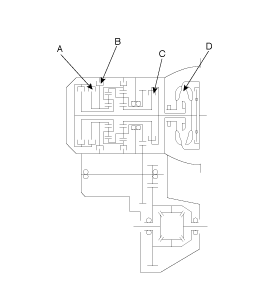
Stall speed is too high in both "D" and "R" ranges
Low line pressure
Low & reverse brake(B) slippage
Stall speed is to high in "D" range only
Underdrive clutch(C) slippage
Stall speed is too high in "R" range only
Reverse clutch(A) slippage
Stall speed too low in both "D" and "R" ranges
Malfunction of torque converter(D)
Insufficient engine output

Warm up the engine until the automatic transaxle fluid temperature is 80-100°C.
Jack up the vehicle so that the wheels are free to turn.
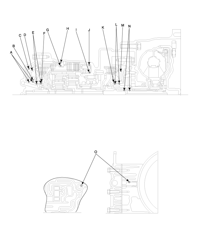
Connect the special tool (oil pressure gauge) to each pressure discharge port.
Measure the hydraulic pressure at each port under the conditions given in the standard hydraulic pressure table, and check that the measured values are within the standard value ranges.
If a value is outside the standard range, correct the problem while referring to the hydraulic pressure test diagnosis table.
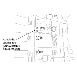
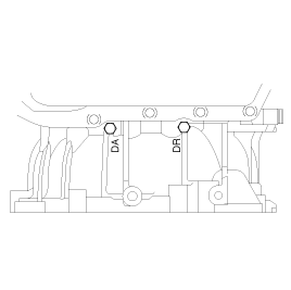
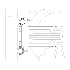
Measurement condition | Standard hydraulic pressure kPa (psi) | ||||||||
Selector lever position | Shift position | Engine speed (rpm) | Underdrive clutch pressure (UD) | Reverse clutch pressure (REV) | Overdrive clutch pressure (OD) | Low and reverse brake pressure (LR) | Second brake pressure (2ND) | Damper clutch apply pressure (DA) | Damper clutch release pressure (DR) |
P | - | 2,500 | - | - | - | 260 ~ 340 | - | - | 220 ~ 360 |
R | Reverse | 2,500 | - | 1,270 ~ 1,770 | - | 1,270 ~ 1,770 | - | - | 500 ~ 700 |
N | Neutral | 2,500 | - | - | - | 260 ~ 340 | - | - | 220 ~ 360 |
D | 1st gear | 2,500 | 1,010 ~ 1,050 | - | - | 1,010 ~ 1,050 | - | - | 500 ~ 700 |
2nd gear | 2,500 | 1,010 ~ 1,050 | - | - | - | 1,010 ~ 1,050 | - | 500 ~ 700 | |
3rd gear | 2,500 | 780 ~ 880 | - | 780 ~ 880 | - | - | More than 750 | 450 ~ 650 | |
4th gear | 2,500 | - | - | 780 ~ 880 | - | 780 ~ 880 | More than 750 | 450 ~ 650 | |
Trouble symptom | Probable cause |
All hydraulic pressures are high | Incorrect transmission control cable adjustment |
Malfunction of the regulator valve | |
All hydraulic pressures are low | Incorrect transmission control cable adjustment |
Malfunction of the oil pump | |
Clogged oil filter | |
Clogged oil cooler | |
Malfunction of the regulator valve | |
Malfunction of the relief valve | |
Incorrect valve body installation | |
Hydraulic pressure is abnormal in "R" range only | Malfunction of the regulator valve |
Clogged orifice | |
Incorrect valve body installation | |
Hydraulic pressure is abnormal in "3" or "4" range only | Malfunction of the regulator valve |
Clogged orifice | |
Incorrect valve body installation | |
Malfunction of the overdrive solenoid valve | |
Malfunction of the overdrive pressure control valve | |
Malfunction of the regulator valve | |
Malfunction of the switch valve | |
Clogged orifice | |
Incorrect valve body installation | |
Only underdrive hydraulic pressure is abnormal | Malfunction of the oil seal K |
Malfunction of the oil seal L | |
Malfunction of the oil seal M | |
Malfunction of the underdrive solenoid valve | |
Malfunction of the underdrive pressure control valve | |
Malfunction of check ball | |
Clogged orifice | |
Incorrect valve body installation | |
Only reverse clutch hydraulic pressure is abnormal | Malfunction of the oil seal A |
Malfunction of the oil seal B | |
Malfunction of the oil seal C | |
Clogged orifice | |
Incorrect valve body installation | |
Only overdrive hydraulic pressure is abnormal | Malfunction of the oil seal D |
Malfunction of the oil seal E | |
Malfunction of the oil seal F | |
Malfunction of the overdrive solenoid valve | |
Malfunction of the overdrive pressure control valve | |
Malfunction check ball | |
Clogged orifice | |
Incorrect valve body installation | |
Only low and reverse hydraulic pressure is abnormal | Malfunction of the oil seal I |
Malfunction of the oil seal J | |
Malfunction of the low and reverse solenoid valve | |
Malfunction of the low and reverse pressure control valve | |
Malfunction of the switch valve | |
Malfunction of the fail safe valve A | |
Malfunction of check ball | |
Clogged orifice | |
Incorrect valve body installation | |
Only second hydraulic pressure is abnormal | Malfunction of the oil seal G |
Malfunction of the oil seal H | |
Malfunction of the oil seal O | |
Malfunction of the second solenoid valve | |
Malfunction of the second pressure control valve | |
Malfunction of the fail safe valve B | |
Clogged orifice | |
Incorrect valve body installation | |
Only reverse clutch hydraulic pressure is abnormal | Malfunction of the oil cooler |
Malfunction of the oil seal N | |
Malfunction of the damper clutch control solenoid valve | |
Malfunction of the damper clutch control valve | |
Malfunction of the torque converter pressure control valve | |
Clogged orifice | |
Pressure applied to non operating element | Incorrect valve body installation |
Incorrect transmission control cable adjustment | |
Malfunction of the manual valve | |
Malfunction of check ball | |
Incorrect valve body installation |
Symptom | Suspect area | Remedy |
Vibration, noise | Loose or damaged transaxle and engine mounts | Tighten or replace mounts |
Inadequate shaft end play | Correct end play | |
Worn or damaged gears | Replace gear | |
Inadequate grade of oil | Replace with specified oil | |
Low oil level | Replenish | |
Inadequate engine idle speed | Adjust idle speed | |
Oil leakage | Broken or damaged, oil seal or O-ring | Replace oil seal or O-ring |
Hard shift | Faulty control cable | Replace control cable |
Poor contact or wear of synchronizer ring and gear cone | Correct or replace | |
Weakened synchronizer spring | Replace synchronizer spring | |
Inadequate grade of oil | Replace with specified oil | |
Grease in flywheel | Inspect and replace flywheel | |
Jumps out of gear | Worn gear shift fork or broken poppet spring | Replace shift fork or poppet spring |
Synchronizer hub to sleeve spline clearance too large | Replace synchronizer hub and sleeve | |
Rear wheel lock at starting with steering wheel full-turn | 4WD ECM malfunction | Replace 4WD ECM |
Rear wheel lock at starting with half-pressing clutch and acceleration pedal |