Has a problem been found?

▶ Repair as necessary and go to "Verification of Vehicle Repair" procedure.

▶ Go to "Ground Circuit Inspection" procedure.
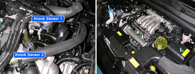
The knock sensor is attached to the cylinder block and senses engine knocking. The sensor contains a piezoelectric element that converts vibration (or noise) into voltage signal and sends this signal to ECM. With input signals from camshaft position and crankshaft position sensor, ECM can identify which cylinder is knocking. ECM filters vibrations and determines if the vibrations are knocking signal. The Engine Control Module (ECM) uses this signal to suppress knocking by retarding ignition timing. The ECM will set a code (Malfunction Indicator Lamp will Not turn on) if during two driving cycles the Knock sensor's output voltage falls below minimum threshold. This code indicates an unexpected vibration is being read by the Knock sensor or ECM under normal engine operation.
The ECM monitors the range of the analog input signal from knock sensor to check sensor failure that is short circuit or open circuit. If the difference between knock signal and noise level is smaller than the threshold during defined time period, the DTC P0325 is set. In case the noise level is higher than the upper threshold or lower than the lower threshold, the DTC P0325 is set too.
Item | Detecting Condition | Possible Cause |
DTC Strategy | ● Voltage Range Check | ● Open/short in signal or ground circuit ● Contact resistance in connectors ● Faulty knock sensor |
Enable Conditions | ● Knock control enabled● Engine speed >1800 rpm | |
Threshold Value | ● Mean value of sensor signal < 0.1V | |
Diagnostic Time | ● 10*720 crank angle |
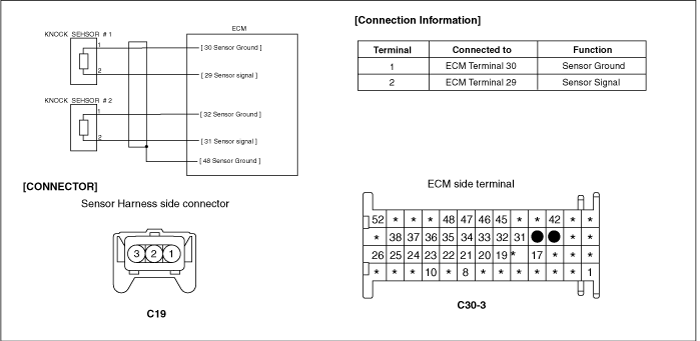
Many malfunctions in the electrical system are caused by poor harness(es) and terminals. Faults can also be caused by interference from other electrical systems, and mechanical or chemical damage.
Thoroughly check connectors for looseness, poor connection, bending, corrosion, contamination, deterioration, or damage.
Has a problem been found?

▶ Repair as necessary and go to "Verification of Vehicle Repair" procedure.

▶ Go to "Ground Circuit Inspection" procedure.
Ignition "OFF".
Disconnect Knock sensor connector.
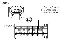
Measure resistance between terminals 1 of the sensor harness connector and 30 of the ECM harness connector.
Specification : Approx. 0Ω
Is resistance within the specification?

▶ Go to "Signal Circuit Inspection" procedure.

▶ Check for an open in the ground circuit. Repair as necessary and go to "Verification of Vehicle Repair" procedure.
Check for open in signal harness.
Ignition "OFF".
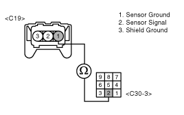
Measure resistance between terminals 2 of the sensor harness connector and 29 of the ECM harness connector.
Specification : Approx. 0Ω
Is resistance within the specification?

▶ Go to next step as below

▶ Repair as necessary and go to "Verification of Vehicle Repair" procedure.
Check for short to ground in signal harness.
Ignition "OFF"
Measure resistance between terminal 2 of the sensor harness connector and chassis ground
Specification : Infinite
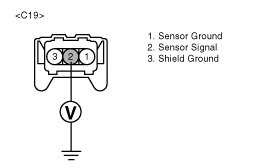
Is resistance within the specification?

▶ Go to next step as below

▶ Repair as necessary and go to "Verification of Vehicle Repair" procedure.
Check for short to power in signal harness.
Ignition "OFF"
Disconnect ECM connector
Ignition "ON" & Engine "OFF"
Measure voltage between terminal 2 of the sensor harness connector and chassis ground
Specification : Approx. 0V

Is voltage within the specification?

▶ Go to "Component Inspection" procedure

▶ Repair as necessary and go to "Verification of Vehicle Repair" procedure.
Component resistance inspection.
Ignition "OFF"
Disconnect knock sensor connector
Measure resistance between terminals 1 and 2 of the sensor connector(Component side).
Specification : Approx. 5㏁ at 20℃(68℉)
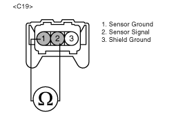
Output signal inspection
Remove knock sensor from vehicle and secure (across mounting boss) in a shop vise.
Set up an oscilloscope as follows :
Channel A (+): terminal 2 (-): terminal 1
Rap on vise with a ball peen hammer while monitoring oscilloscope screen (there should be a spike of less than 1 volt with each hammer strike).
Specification : knock sensor send a voltage spike with hammer strikes
Installation torque inspection.
Check the installation torque of the knock sensor.
Specification : Approx. 16 ~ 28N·m(160~250 kg·cm,11.8~18.4 lb·ft)
Has a problem been found?

▶ Check knock sensor for contamination, deterioration, or damage. Substitute with a known-good knock sensor and check for proper operation. If the problem is corrected, replace knock sensor and then go to "Verification of Vehicle Repair" procedure.

▶ Check for poor connection between ECM and component: backed out terminal, improper mating, broken locks or poor terminal to wire connection. Repair as necessary and go to "Verification of Vehicle Repair" procedure.
After a repair, it is essential to verify that the fault has been corrected.
Connect scan tool and select "Diagnostic Trouble Codes(DTCs)" mode.
Press F4(DTAL) and confirm that "DTC Readiness Flag" indicates "Complete". If not, drive the vehicle within conditions noted in the freeze frame data or enable conditions.
Read "DTC Status" parameter.
Is parameter displayed "History(Not Present) fault"?

▶ System performing to specification at this time. Clear the DTC

▶ Go to the applicable troubleshooting procedure.