Has a problem been found?

Repair as necessary and go to "Verification of Vehicle Repair" procedure.

Go to "Signal Circuit Inspection" procedure.
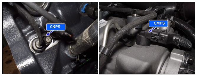
The crankshaft angular sensor detects and counts the teeth on the crankshaft and provides ECM with the information on the current position of crank angle and cylinder. This signal is fed to ECM to be used to determine the engine speed and adjust the fuel injection timing. The camshaft position sensor detects the teeth target wheel and provides ECM with the information on the current position of piston and cylinder.
This signal is fed to ECM to be used to determine the sequence of fuel injection.
In case of the the crankshaft angular sensor or the camshaft position sensor failure, the engine symptoms will occur a running engine stall, starting impossible and rough idle with noise.
If the difference between actual CKP value and calculated CKP value is generated, the ECM judged this as a fault and DTC is set.
Item | Detecting Condition | Possible Cause |
DTC Strategy | ● Signal check | ● Open or short to signals(+,-) harness ● Open in ground harness ● Faulty CKP ● Faulty CKP tone wheel ● Faulty ECM |
Enable Conditions | ● Engine run | |
Threshold Value | ● Crank angular with acceleration or deceleration is out of allowed limits (dynamic plausibility) | |
Diagnostic Time | ● 0.09 sec. | |
MIL Fuel Limit Fuel Cut EGR Off | ● No ● No ● Yes ● No |
CKP | |
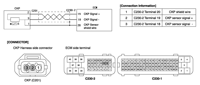
Resistance | 860 ± 10% Ω at 20°C |
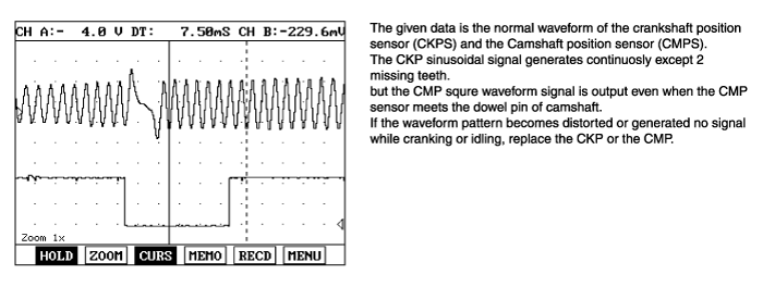
Connect scantool to Data Link Cable (DLC).
Warm up engine to normal operating temperature.
Monitor "Acceleration Position Sensor & Engine Speed" parameter on the scantool .
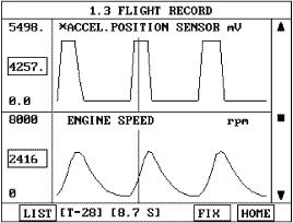
Fig 1) APS signal and engine speed increase when depressing accel pedal.
Is the Current data displayed correctly ?

Fault is intermittent caused by poor contact in the sensor’s and/or ECM’s connector or was repaired and ECM memory was not cleared. Thoroughly check connectors for looseness, poor connection, bending, corrosion, contamination, deterioration, or damage. Repair or replace as necessary and go to "Verification of Vehicle Repair" procedure.

▶ Go to "W/Harness Inspection" procedure.
Many malfunctions in the electrical system are caused by poor harness and terminals..
Faults can also be caused by interference from other electrical systems, and mechanical or chemical damage.
Thoroughly check connectors for looseness, poor connection, bending, corrosion, contamination, deterioration, or damage.
Has a problem been found?

Repair as necessary and go to "Verification of Vehicle Repair" procedure.

Go to "Signal Circuit Inspection" procedure.
Check for open or short in signal (+) harness
Ignition "OFF" & Engine "OFF".
Disconnect CKP sensor connector.
Ignition "ON" & Engine "OFF".
Measure voltage between terminal 2 of the sensor harness connector and chassis ground.
Specification : Approx. 2.5V
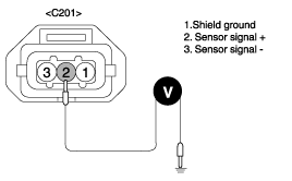
Is the measured voltage within specifications ?

▶ Go to "Check for open or short in signal(-) harness" as below.

▶ Check for open or short in signal(+) harness.
Repair as necessary and go to "Verification of Vehicle Repair" procedure.
Check for open or short in signal (-) harness
Ignition "OFF" & Engine "OFF".
Disconnect CKP sensor connector.
Ignition "ON" & Engine "OFF".
Measure voltage between terminal 3 of the sensor harness connector and chassis ground.
Specification : Approx. 2.5V
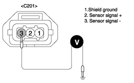
Is the measured voltage within specifications ?

▶ Go to "Ground Circuit Inspection" procedure.

▶ Check for open or short in signal(-) harness.
Repair as necessary and go to "Verification of Vehicle Repair" procedure.
Ignition "OFF" & Engine "OFF".
Disconnect CKP sensor and ECM connector.
Measure resistance between terminal 1 of the sensor harness connector and terminal 20 of ECM harness connector.
Specification : Approx. below 1Ω
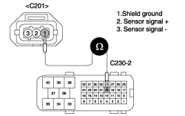
Is the measured resistance within specifications ?

▶ Go to "Component Inspection" procedure.

▶ Check for open in harness.
Repair as necessary and go to "Verification of Vehicle Repair" procedure.
Check tone wheel.
Ignition "OFF" & Engine "OFF".
Remove CKPS.
Visually check that Tone wheel is O.K through the installation hole for CKPS.
Is the Tone wheel installed on the crankshaft O.K ?

▶ Go to "Check CKPS" as below.

▶ Check Tone wheel for contamination, deterioration or damage.
Replace Tone wheel on the crankshaft as necessary and go to "Verification of Vehicle Repair" procedure.
Check CKPS
Ignition "OFF".
Remove CKPS and then connect CKPS connector to CKPS.
Ignition "ON" & Engine "OFF".
Move a metal on the detecting edge of CKPS with monitoring signal waveform.
Is the signal waveform displayed ?

▶ Substitute with a known-good ECM and check for proper operation. If the problem is corrected, replace ECM and then go to "Verification of Vehicle Repair" procedure.

▶ Substitute with a known-good CMPS and check for proper operation. If the problem is corrected, replace CMPS and then go to "Verification of Vehicle Repair" procedure.
After a repair, it is essential to verify that the fault has been corrected.
Connect scan tool and select "Diagnostic Trouble Codes(DTCs)" mode and then clear DTC.
Operate the vehicle within DTC Enable conditions in General information.
Are any DTCs present ?

Go to the applicable troubleshooting procedure.

System is performing to specification at this time.