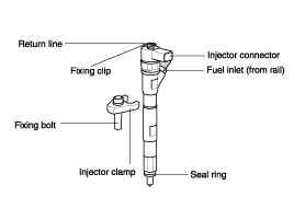
The start of injection and the injected fuel quantity are adjusted by electrically triggered injectors. These injectors supersede the nozzle-and-holder assembly (nozzle and nozzle-holder). Similar to the already existing nozzle-holder assemblies in direct-injection (DI) diesel engines, clamps are preferably used for installing the injectors in the cylinder head. This means that the Common Rail injectors can be installed in already existing DI diesel engines without major modifications to the cylinder head.

The hole-type nozzle
The hydraulic servo-system
The solenoid valve
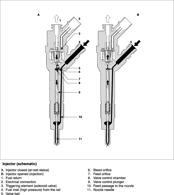
Fuel is fed from the high-pressure connection to the nozzle through the passage,and to the control chamber through the feed orifice. The control chamber isconnected to the fuel return via a bleed orifice which is opened by the solenoidvalve.
With the bleed orifice closed, the hydraulic force applied to the valve controlplunger exceeds that at the nozzle-needle pressure shoulder. As a result,the needle is forced into its seat and seals off the high-pressure passagefrom the combustion chamber.
When the injector's solenoid valve is triggered, the bleed orifice is opened.This leads to a drop in control-chamber pressure and, as a result, the hydraulicpressure on the plunger also drops. As soon as the hydraulic force drops belowthe force on the nozzle-needle pressure shoulder, the nozzle needle opensand fuel is injected through the spray holes into the combustion chamber.This indirect control of the nozzle needle using a hydraulic force-amplificationsystem is applied because the forces which are necessary for opening the needlevery quickly cannot be directly generated by the solenoid valve. The so-calledcontrol quantity needed for opening the nozzle needle is in addition to thefuel quantity which is actually injected, and it is led back to the fuel-returnline via the control chamber's orifices.
In addition to the control quantity, fuel is also lost at the nozzle-needleand valve-plunger guides. These control and leak-off fuel quantities are returnedto the fuel tank via the fuel return and the collector line to which overflow valve, high-pressure pump, and fuel pressure control valve and also connected.

The injector's operation can be subdivided into four operating states withthe engine running and the high-pressure pump generating pressure:
Injector closed (with high pressure applied)
Injector opens (start of injection)
Injector opened fully
Injector closes (end of injection)
These operating states result from the distribution of the forces appliedto the injector's components. With the engine at stand still and no pressurein the rail, the nozzle spring closes the injector.
In the at-rest state, the solenoid valve is not energized and is thereforeclosed (See "A" IN Figure). With the bleed orifice closed, the valve springforces the armature's ball ontothe bleed orifice seat. The rail's high pressurebuilds up in the valve control chamber, and the same pressure is also presentin the nozzle's chamber volume. The rail pressure applied at the control plunger'send face, together with the force of the nozzle spring, maintain the nozzlein the closed positionagainst the opening forces applied to its pressure stage.
The injector is in its at-rest position. The solenoid valve is energized withthe pickup current which serves to ensure that it opens quickly (See "B" inFigure). The force exerted by the triggered solenoid now exceeds that of thevalve spring and the armature opens the bleed orifice. Almost immediately,the high-level pick-up current is reduced to the lower holding current requiredfor the electromagnet. This is possible due to the magnetic circuit's airgap now being smaller. When the bleed orifice opens, fuel can flow from thevalve-control chamber into the cavity situated above it, and from there viathe fuel return to the fuel tank, The bleed orifice prevents complete pressurebalance, and the pressure in the valve control chamber sinks as a result.This leads to the pressure in the valve-control chamber being lower than thatin the nozzle's chamber causes a reduction in the force exerted on the controlplunger, the nozzle needle opens as a result, and injection starts. The nozzleneedle's opening speed is determined by the difference in the flow rate throughthe bleed and feed orifices. The control plunger reaches its upper stop whereit remains supported by a cushion of fuel which is generated by the flow offuel between the bleed and feed orifices. The injector nozzle has now openedfully, and fuel is injected into the combustion chamber at a pressure almostequal to that in the fuel rail. Force distribution in the injector is similarto that during the opening phases.
As soon as the solenoid valve is no longer triggered, the valve spring forcesthe armature downwards and the ball closes the bleed orifice. The armatureis a 2-piece design. Her, although the armature plate is guided by a drivershoulder in its downward movement, it can "over spring" with the return springso that it exerts no downwards-acting forces on the armature and the ball.This closing of the bleed orifice leads to pressure build up in the controlchamber via the input from the feed orifice. This pressure is the same asthat in the rail and exerts an increased force on the control plunger throughits end face. This force, together with that of the spring, now exceeds theforce exerted by the chamber volume and the nozzle needle closes. The nozzleneedle's closing speed is determined by the flow through the feed orifice.Injection ceases as soon as the nozzle needle comes up against its bottomstop again.