3.
Has a problem been found?

Repair as necessary and go to "Verification of Vehicle Repair" procedure.

Go to " Power Circuit Inspection " procedure.
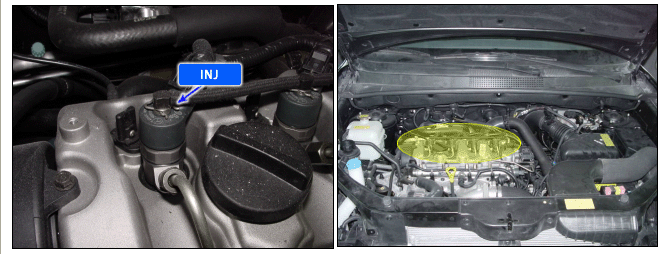
Special injectors with hydraulic servo-system and electrical triggering element (solenoid valve) are used with the common rail system in order to achieve efficient start of injection and precise injected fuel quantity.
Metering and spray preparation of the diesel fuel, as needed by the engine according to the engine map, Realization of pilot and main injection and post injection if required.
Pilot injection is used to reduce the engine noise and vibration and post injection is used to reduce the NO and N0X in the exhaust gas.
Control of injected quantity and injection timing based on the system pressure and enerizing time as actuated by the ECM. The injected fuel quantity is now defined by the injector opening time and rail pressure.
Injection is terminated when the solenoid valve is no longer triggered and closes as a result.
In case of more than 2 injectors failure, the engine symptoms will occur the running engine stall and the starting impossible.
If the signal below threshold value, the ECM judged this as a fault and DTC is set.
Item | Detecting Condition | Possible Cause |
DTC Strategy | ● Circuit continuity check | ● Open in power circuit ● Short to ground in control circuit ● Open in control circuit ● Faulty injector ● Faulty ECM |
Enable Conditions | ● Engine run | |
Threshold Value | ● Load drop error : load drop is detected if during energizing the minimum current/min = 3A is not reached ● Fast current decrease error : a fixed time after the energizing period the current has to decrease below/min = 3A | |
Diagnostic Time | ● 0.3 sec. | |
MIL Fuel Limit Fuel Cut EGR Off | ● Yes ● Yes ● No ● No |
Injector | |
Resistance | 0.365 ± 0.055 Ω at 20°C |
Connect scantool to Data Link Cable (DLC).
Warm up engine to normal operating temperature.
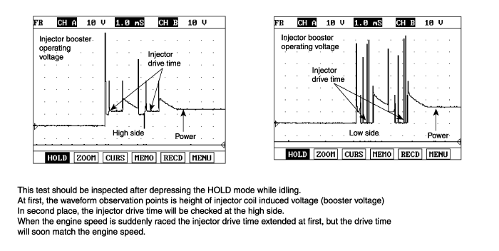
Monitor that "Injector Booster Operating Voltage" parameter on the scantool.
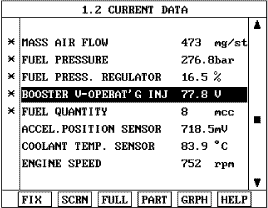
Fig 1) Normal value with injector booster operating voltage (above 70V).
Is Current data displayed correctly ?
Fault is intermittent caused by poor contact in the sensor’s and/or ECM’s connector or was repaired and ECM memory was not cleared. Thoroughly check connectors for looseness, poor connection, bending, corrosion, contamination, deterioration, or damage. Repair or replace as necessary and go to "Verification of Vehicle Repair" procedure.
▶ Go to "W/Harness Inspection" procedure.
Many malfunctions in the electrical system are caused by poor harness and terminals.
Faults can also be caused by interference from other electrical systems, and mechanical or chemical damage.
Thoroughly check connectors for looseness, poor connection, bending, corrosion, contamination, deterioration, or damage.
Has a problem been found?
Repair as necessary and go to "Verification of Vehicle Repair" procedure.
Go to " Power Circuit Inspection " procedure.
Ignition "OFF".
Disconnect injector and ECM connector.
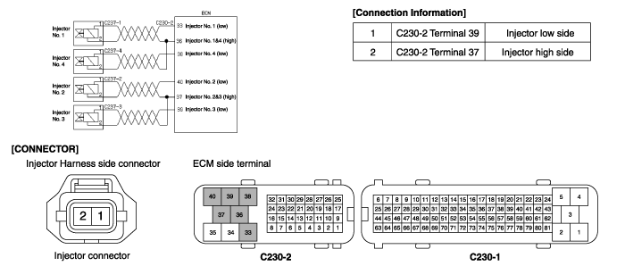
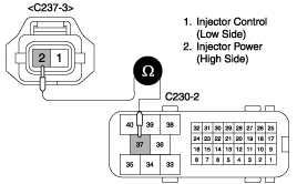
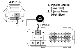
Measure resistance between terminal 2 of injector harness connector and terminal 37 of ECM harness connector.
Specification : Approx. below 1Ω
Is the measured resistance within specifications ?
▶ Go to "Control Circuit Inspection" procedure.
▶ Check for open in the power harness.
Repair as necessary and go to "Verification of Vehicle Repair" procedure.
Check for short to ground in harness
Ignition "OFF".
Disconnect injector connector.
Ignition "ON" & Engine "OFF".
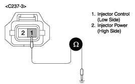
Measure resistance between terminal 1 of injector harness connector and chassis ground.
Specification : Infinite
Is the measured resistance within specifications ?
▶ Go to " Check for open in harness" as below.
▶ Check for short to ground in the control harness.
Repair as necessary and go to "Verification of Vehicle Repair" procedure.
Check for open in harness
Ignition "OFF".
Disconnect injector and ECM connector.
Measure resistance between terminal 1 of injector harness connector and terminal 39 of ECM harness connector
Specification : Approx. below 1Ω
Is the measured resistance within specifications ?
▶ Go to "Component Inspection" procedure.
▶ Check for open in the control harness.
Repair as necessary and go to "Verification of Vehicle Repair" procedure
Ignition "OFF"
Disconnect Injector connector.
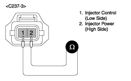
Measure resistance between terminal 1 and 2 of injector connector (Component side).
Specification : 0.365Ω ± 0.055(20°C)
Is the measured resistance within specifications ?
▶ Substitute with a known-good ECM and check for proper operation.
If the problem is corrected, replace ECM and then go to "Verification of Vehicle Repair" procedure."
▶ Check injector for deterioration, or damage.
Substitute with a known-good injector and check for proper operation.
If the problem is corrected, replace injector and then go to "Verification of vehicle Repair" procedure.
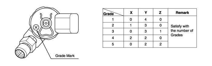
Before replacing injector, be sure that grade mark(X,Y,Z) should be satisfied with combination as below.
After a repair, it is essential to verify that the fault has been corrected.
Connect scan tool and select "Diagnostic Trouble Codes(DTCs)" mode and then clear DTC.
Operate the vehicle within DTC Enable conditions in General information.
Are any DTCs present ?
Go to the applicable troubleshooting procedure.
System is performing to specification at this time.
