3.
Has a problem been found?

Repair as necessary and go to "Verification of Vehicle Repair" procedure.

Go to " Power Circuit Inspection " procedure.
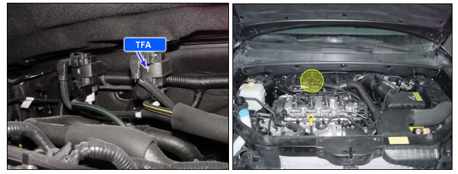
By actuating of flaps in the intake passage the passage at the inlet valve of the cylinder can be narrowed.
This reduces the air flow. The flaps in the intake passage are controlled by the intake throttle actuator.
Calculation of the duty cycle for the inlet passage shut-off can switched on and off by the function switch of the inlet passage shut off.
If the engine speed and the demand quantity + low idle governor exceed certain thresholds, also the MAFS signal must be above a threshold. If this is not the case, the error "flap blocked closed" is recognized.
If the engine speed and the control duty cycle exceed certain thresholds, the digital switch of the inlet passage shut off must be actuated. If it is, the error flap blocked open is recognized.
In case of the throttle actuator stuck, the engine symptoms will occur a running engine stall and a starting impossible.
If the signal generates threshold value, the ECM judged this as a fault and DTC is set.
Item | Detecting Condition | Possible Cause |
DTC Strategy | ● Circuit continuity check | ● Open or short in power circuit ● Open or short in control circuit ● Faulty throttle actuator ● Faulty ECM |
Enable Conditions | ● Engine run | |
Threshold Value | ● Open or short for relay control circuit | |
Diagnostic Time | ● 0.48 sec. | |
MIL Fuel Limit Fuel Cut EGR Off | ● No ● No ● No ● Yes |
Connect scantool to Data Link Cable (DLC).
Warm up engine to normal operating temperature.
Monitor that " Intake Throttle Actuator " parameter on the scantool.
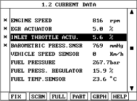
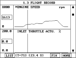
Fig 1) Normal value with intake throttle actuator at idle.
Fig 2) Normal value with intake throttle actuator and engine speed while accelerating and decelerating.
Is the Current data displayed correctly ?
▶ Fault is intermittent caused by poor contact in the sensor’s and/or ECM’s connector or was repaired and ECM memory was not cleared. Thoroughly check connectors for looseness, poor connection, bending, corrosion, contamination, deterioration, or damage. Repair or replace as necessary and go to "Verification of Vehicle Repair" procedure.
▶ Go to "W/Harness Inspection" procedure.
Many malfunctions in the electrical system are caused by poor harness and terminals.
Faults can also be caused by interference from other electrical systems, and mechanical or chemical damage.
Thoroughly check connectors for looseness, poor connection, bending, corrosion, contamination, deterioration, or damage.
Has a problem been found?
Repair as necessary and go to "Verification of Vehicle Repair" procedure.
Go to " Power Circuit Inspection " procedure.
Check for short in harness
Ignition "OFF".
Disconnect MAF sensor connector.
Ignition "ON" & Engine "OFF".
Measure voltage between terminal "2" of the sensor harness connector and chassis ground.
Specification : 4.8V ~ 5.1V
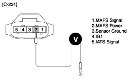
Is the measured voltage within specifications ?
▶ Go to "Component Inspection" procedure.
▶ Check for short to battery or ground in the MAFS power harness.
Repair as necessary and go to "Verification of Vehicle Repair" procedure.
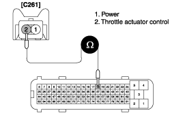
Check for short to battery in harness.
Ignition "OFF".
Disconnect throttle acutator connector.
Ignition " ON" & Engine " OFF".
Measure voltage between terminal 2 of the throttle actuator harness connector and chassis ground.
Specification : Approx. below 1V
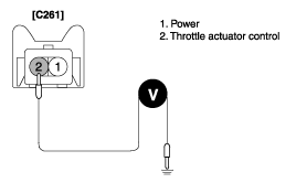
Is the measured voltage within specificaitons ?
▶ Go to " Check for short to ground in harness " as below.
▶ Check for short to battery in control harness.
Repair as necessary and go to "Verification of Vehicle Repair" procedure.
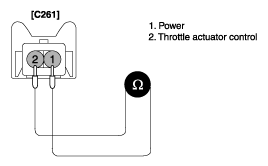
Check for short to ground in harness.
Ignition "OFF".
Disconnect throttle acutator connector.
Measure voltage between terminal 2 of the throttle actuator harness connector and chassis ground.
Specification : Infinite
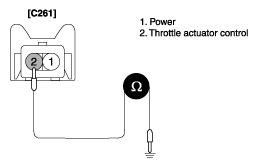
Is the measured resistance within specifications ?
▶ Go to " Check for open in harness " as below.
▶ Check for short to ground in control harness.
Repair as necessary and go to "Verification of Vehicle Repair" procedure .
Check for open in harness.
Ignition "OFF" & Engine "OFF".
Disconnect Throttle actuator and ECM connector.
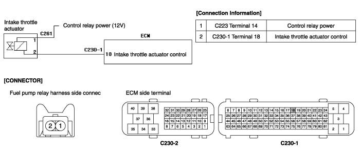
Measure resistance between terminal 2 of the sensor harness connector and ECM(37) harenss connector.
Specification : Approx. below 1Ω
Is the measued resistance within specifications ?
▶ Go to "Component Inspection" procedure.
▶ Check for open in harness.
Repair as necessary and go to "Verification of of Vehicle Repair" procedure .
Check Throttle actuator.
Ignition "OFF".
Disconnect Throttle actuator.
Measure resistance between terminal 1 and 2 of throttle actuator connecor(Component side).
Specification : 14 ~ 17 Ω ( 20°C)
Is the measued resistance within specifications ?
▶ Go to "Check Throttle Actuator Operation" as below.
▶ Substitute with a known-good throttle actuator and check for proper operation.
If the problem is corrected, replace throttle actuator and then go to "Verification of Vehicle Repair" procedure.
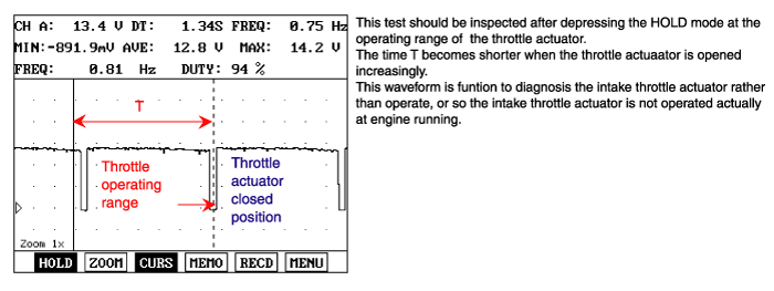
Check Throttle actuator Operation.
Ignition "ON" & Engine "ON".
Check that operating duty of throttle actuator is around 5% at idle.
Check that vaccum is felt after disconnecting vaccum hose from throttle actuator valve.
Check that vaccum is felt at the moment after ignition off.
Operating Duty of Throttle actuator : 5% | Operating Duty of Throttle actuator : 95% |
No vaccum (Close valve) | Vaccum (Open valve) |
Is the vaccum felt according to the operating duty of throttle actuator ?
▶ Substitute with a known-good ECM and check for proper operation.
If the problem is corrected, replace ECM and then go to "Verification of Vehicle Repair" procedure.
▶ Thoroughly check connectors for looseness, poor connection, bending, corrosion, contamination, deterioration, or damage. Repair or replace as necessary and go to "Verification of Vehicle Repair" procedure .
After a repair, it is essential to verify that the fault has been corrected.
Connect scan tool and select "Diagnostic Trouble Codes(DTCs)" mode and then clear DTC.
Operate the vehicle within DTC Enable conditions in General information.
Are any DTCs present ?
Go to the applicable troubleshooting procedure.
System is performing to specification at this time.
