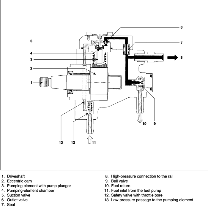
The high-pressure pump is the interface between the lowpressure and the high-pressure stages. Under all operating conditions, it is responsible for providing adequate high-pressure fuel through out the vehicle's complete service life. This also includes the provision of extra as needed for rapid starting and for rapid build-up of pressure in the rail. The high pressure pump continually generates the system pressure as needed in the high-pressure accumulator (common rail). This means therefore, that in contrast to conventional systems, the fuel does not have to be specially compressed for each individual injection process.

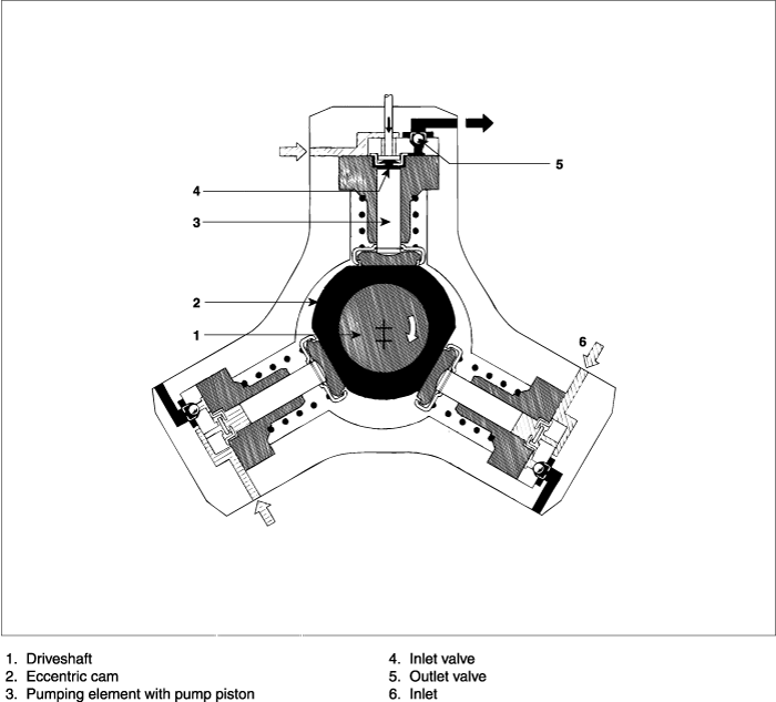
The high-pressure pump is installed preferably at the same point on the diesel engine as a conventional distributor pump. It is driven by the engine (at half engine speed, but max. 3000 rpm) through a coupling, gear wheel, chain, or toothed belt, and lubricated by the diesel fuel pressure control valve is installed directly on the high pressure pump or remote from it. Inside the high pressure pump, the fuel is compressed with theree radially arranged pump pistons which are at an angle of 120° to each other. Since three delivery stokes take place for every revolution, only low peak drive torques are generated so that the stress on the pump drive remains uniform. With 16 N·m, the torque is only about 1/9 of that required to drive a comparable distributor pump. This means that Common Rail places lessloading on the pump drive than is the case with conventional injection system. The power required to drive the pump climbs in proportion to the pressure set in the rail and to the pump's speed (delivery quantity).
For a 2-liter engine turning at rated speed, and with a set pressure of 1,350 bar in the common rail, the high pressure pump requires 3.8kW presuming a mechanical efficiency of approx. 90%. The higher power demand (higher than theoretically necessary) results from the leak-fuel and control quantities at the injector, and from the fuel return through the fuel pressure control valve.

Via a filter with water separator, the fuel pump pumps fuel from the tank to the high-pressure pump through the fuel inlet and the safety valve. It forces the fuel through the safety valve's throttle bore and into the high pressure pump's lubrication and cooling circuit. The driveshaft with its eccentric cams moves the three pump plungers up and down in accordance with the shape of the cam. As soon as the delivery pressure exceeds the safety valve's opening pressure (0.5 ~ 1.5 bar), the fuel pump can force tuel through the high pressure pump's inlet valve into the pumping-element chamber whose pump piston is moving downwards (suction stroke). The inlet valve closes when the pump piston passes through BDC and, since it is impossible for the fuel in the pumping-element chamber to escape, it can now be compressed beyond the delivery pressure.
The increasing pressure opens the outlet valve as soon as the rail pressure is reached, and the compressed fuel enters the high pressure circuit. The pump piston continues to deliver fuel until it reaches TDC (delivery stroke), after which the pressure collapses so that the outlet valve closes. The fuel remaining in the pumping-element chamber drops below the fuel pump pressure, the inlet valve opens and the pumping process starts again.
Since the high-pressure pump is designed for large delivery quantities, excess high pressure fuel is delivered during idle and part-load operation. This excess fuel is returned to the tank via the fuel pressure control valve. The compressed fuel relaxes in the tank, and the energy is lost which was used for compressing the fuel in the first place. In addition to the unnecessary heating up of the fuel, over all efficiency is also reduced. To a certain extent, this loss of efficiency can be compensatd for by switching off one of the pumping elements.
The high-pressure pump's delivery rate is proportional to its rotational speed. And this, in turn, is a function of the engine speed. During the injection-system application-engineering work on the engine, the transmission ratio is defined so that on the one hand the amount of excess fuel is not too high, and on the other, the fuel requirements can still be satisfied during WOT operation. Referred to the crankshaft, transmission ratios of 1:2 and 2:3 are possible.