Check is spark occurs while engine is being cranked.
To prevent gasoline from being injected from injectors during this test, crank the engine for no more then 5~10 seconds at time.
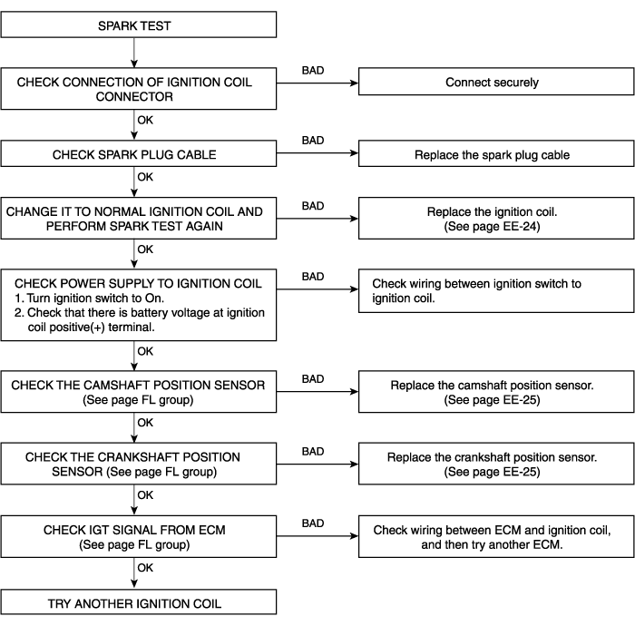
Remove the spark plug cable.
Using a spark plug socket, remove the spark plug.
Remove the ignition coil.
Install the spark plugs to each spark plug cable.
Ground the spark plugs.
Check is spark occurs while engine is being cranked.
To prevent gasoline from being injected from injectors during this test, crank the engine for no more then 5~10 seconds at time.

Using a spark plug socket, install the spark plugs.
Install the spark plug cable and ignition coil.
2.0
Remove the spark plug cable(A).
When removing the spark plug cable, pull on the spark plug cable boot (not the cable), as it may be damaged.
Using a spark plug socket, remove the spark plug(B).
Be careful that no contaminats enter through the spark plug holes.
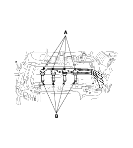
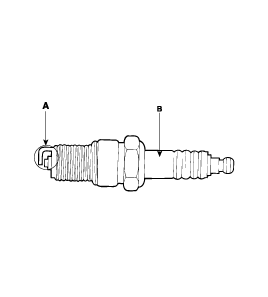
Inspect the electrodes(A) and ceramic insulator(B).
2.7
Remove the engine cover.
Disconnect the VIS actuator connectors and injector connectors.
Remove the accelerator cable.
Remvoe surge tank sub assembly.
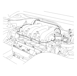
Remove the spark plug cable.
Remvoe the spark plug.
Inspect the electrodes and ceramic insulator.
CONDITION | DARK DEPOSITS | WITHE DEPOSITS |
DESCRIPTION | - Fuel mixture too rich - Low air intake | - Fuel mixture too lean - Advanced ignition timing - Insufficient plug tightening |
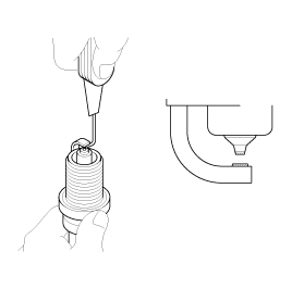
Check the electrode gap(A).
Standard (New)
1.0~1.1 mm (0.039~0.043 in.) - Unleaded
0.7~0.8 mm (0.028~0.031 in) - Leaded
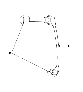
Carefully remove the spark plug cable by pulling on the rubber boots(A).
Check the condition of the spark plug cable terminals(B), if any terminal is corroded, clean it, and if it broken or distorted, replace the spark plug cable.
Connect the ohmmeter probes and measure resistance.
RESISTANCE : 5.6KΩ/m ± 20%
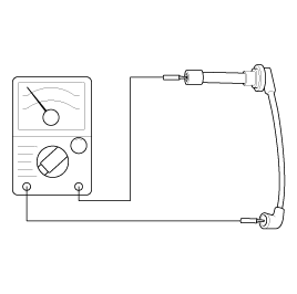
Resistance should not be higher than 10KΩ per meter of cable.
If resistance is higher, replace the cable.
Measure the primary coil resistance between terminals 1-2 and 1-3.
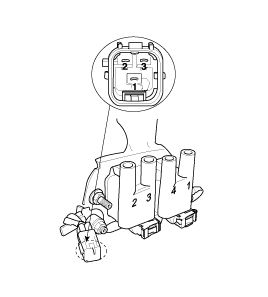
Measure the primary coil resistance between terminals 1-4, 2-4 and 3-4.
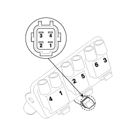
Standard value :
0.58Ω ± 10% (2.0)
0.74Ω ± 10% (2.7)
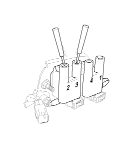
Measure the secondary coil resistance between the high-voltage terminal for the No.1 and No.4 cylinders, and between the high-voltage terminals for the No.2 and No.3 cylinders.
Standard value :
8.8kΩ ± 15% (2.0)
13.3kΩ ± 15% (2.7)
Be sure, when measuring the resistnace of the secondary coil, to disconnect the connector of the ignition coil.
Measure the secondary coil resistance between the high-voltage terminals for the No.1 and No.4 cylinders, No.2 and No.5 cylinders and No.3 and No.6 cylinders.
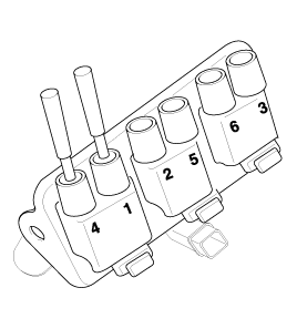
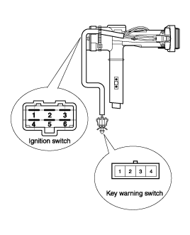
Remove the connector located under the steering column.
Check for continuity between terminals.
If there is no continuity, replace the ignition switch.

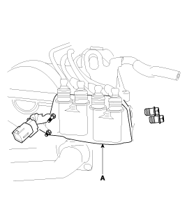
Remove the engine cover.
Disconnect the spark plug cable and connector.
Remove the ignition coil(A).
Installation is the reverse of removal.
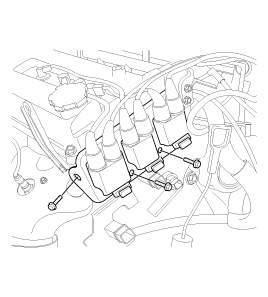
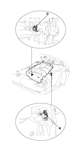
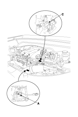
Disconnect the crankshaft position sensor connector.
Remove the crankshaft position sensor(A).
Remove the engine cover.
Disconnect the camshaft position sensor connector.
Remove the camshaft position sensor(C).
