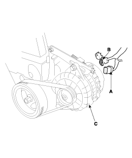
Deisconnect the alternator connector(A) and "B" terminal cable(B) from the alternator(C).
GASOLINE
Disconnect the battery negative terminal first, then the positive terminal.
Deisconnect the alternator connector(A) and "B" terminal cable(B) from the alternator(C).


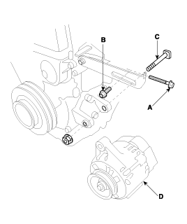
Remove the adjusting bolt(A) and mounting bolt(B), then remove the alternator belt.
Pull out the through bolt(C), then remove the alternator(D).
Installation is the reverse of removal.
Adjust the alternator belt tension after installation (See page EE-40).
DIESEL
Disconnect the battery negative terminal frist, then the positive terminal.
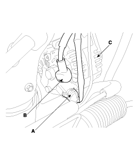
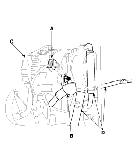
Disconnect the alternator connector(A) and "B" terminal cable(B) from the alternator(C).
Disconnect the vacuum pump hose(D).
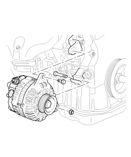
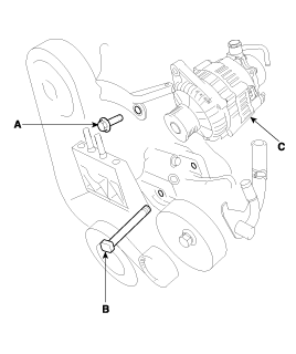
Remove the mounting bolt(A) and through bolt(B), then remove the alternator(C).
Installation is the reverse of removal.
GASOLINE
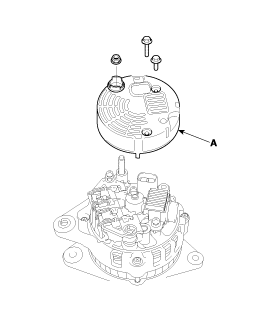
Remove the rear cover(A).
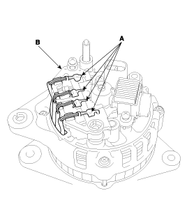
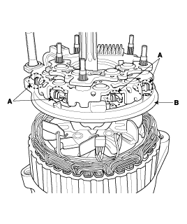
Unsolder the 4 stator leads(A) to the main diodes on the rectifier(B).
When soldering or unsoldering, be careful not to heat the diodes for too long.
Be careful that excesive force is not exerted on the leads of the diodes.
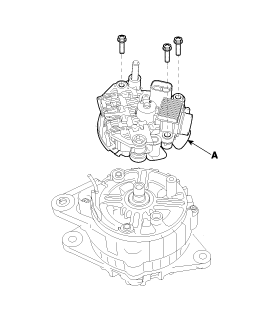
Remove the rectifier assembly(A).
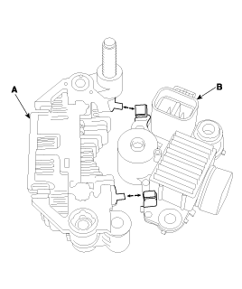
Unsolder between rectifier(A) and brush holder(B).
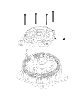
Remove the rear bracket(A).
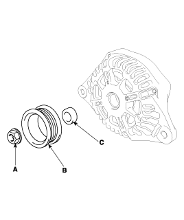
Remove the nut(A), pulley(B) and spacer(C)..
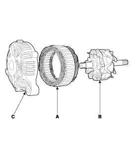
Disconnect the stator(A), rotor(B) and front bracket(C).
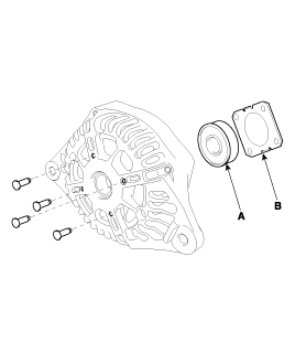
Remove the rear bearing(A) and cover(B).
Reassembly is the reverse or disassembly.
Before the rotor is attached to the rear bracket, insert a wire through the small hole in the rear bracket to lock the brush. After the rotor has been installed, the wire can be removed.
GASOLINE (2.7)
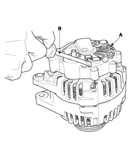
Remove the alternator cover(A) using a screw driver(B).
Loosen the mounting bolts(A) and disconnect the brush holder assembly(B).
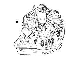
Remove the slip ring guide(A).
Remvoe the nut, pully(A) and spacer.
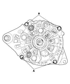
Loosen the 4 through bolts(A).
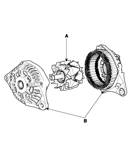
Disconnect the rotor(A) and cover(B).
Reassembly is the reverse of disassembly.
DIESEL
Remove the pulley cover.
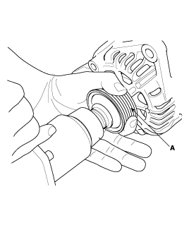
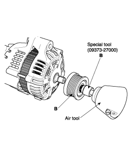
Remove the pulley(A) using the special tool(B).
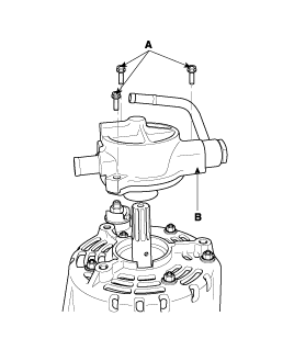
After loosening the three bolts(A). Remove the vacuum pump(B).
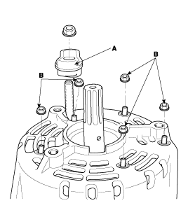
Remove the B terminal insulator(A) and loosen the five rear cover mounting nuts(B).
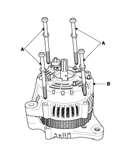
After loosening the four through bolts(A), remove the rear cover(B).
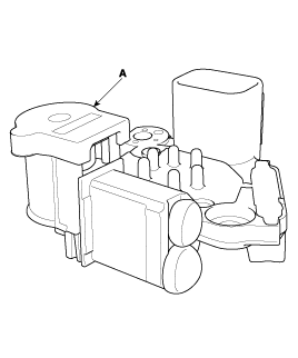
After removing the weld between the stator lead and diode lead(A), remove the regulator assembly(B).
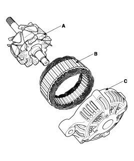
Separate the rotor(A), stator(B), and front cover(C).
Installation is the reverse of removal.
Check that there is continuity between the slip rings(A).
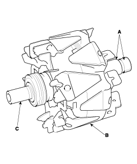
Check that there is no continuity between the slip rings and the rotor(B) or rotor shaft(C).
If the rotor fails either continuity check, replace the alternator.
Check that there is continuity between each pair of leads(A).
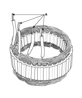
Check that there is no continuity between each lead and the coil core.
If the coil fails either continuity check, replace the generator.
When using a new belt, first adjust the deflection or tension to the values for the new belt, then readjust the deflection or tension to the values for the used belt after running engine for five minutes.
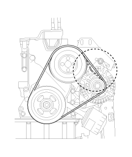
Deflection method :
Apply a force of 98N (10 kgf, 22 lbf), and measure the deflection between the alternator and crankshaft pulley.
Deflection
Used Belt : 5.0 ~ 6.0 mm (0.20 ~ 0.23 in)
New Belt : 4.0 ~ 5.0 mm (0.16 ~ 0.20 in)
If the belt is worn or damaged, replace it.
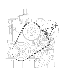
Belt tension gauge method :
Attach the belt tension gauge to the belt and measure the tension. Follow the gauge manufacturer's instructions.
Tension
Used Belt : 340~490 N (35~50 kgf, 77~110 lbf)
New Belt : 540~640 N (55~65 kgf, 121~143 lbf)
If the belt is worn or damaged, replace it.
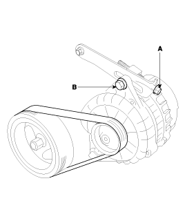
If adjustment is necessary :
Loosen the adjusting bolt(A) and the lock bolt(B).
Move the alternator to obtain the proper belt tension, then retighten the nuts.
Recheck the deflection or tension of the belt.