The EGR (Exhaust Gas Recirculation) system is used to divert some of the exhaust gas to the engine inlet system in order to reduce an excess of air and the temperature in the combustion chamber.
This device also significantly reduces emissions of the nitric oxide at the exhaust.
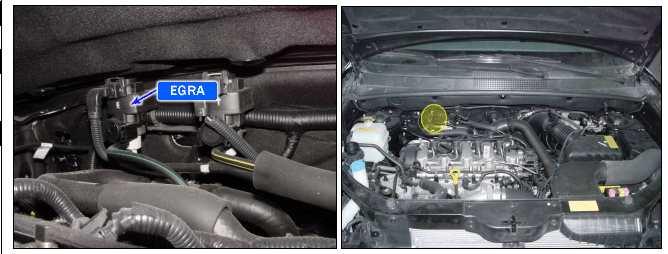
The EGR system is composed of a solenoid valve, a proportional pneumatic valve and an air flow meter.
The EGR solenoid valve controls the opening and closing the pneumatic valve using the low pressure from the braking assistance circuit. The low pressure is created by the vaccum pump located at the end of the alternator.
The duty control of the solenoid valve is determined by the injection computer depending on the air flow requested.
In case of EGR solenoid valve failure, the engine performance will be reduced.
DTC DESCRIPTION
If the signal exceeds threshold value, the ECM judged this as a fault and DTC is set.
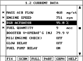
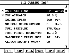
Monitor that "Mass Air Flow Sensor" parameter on the scantool is changing without EGR actuator operation or with EGR actuator operation while idling engine speed.
FIG 1
FIG 2
Fig 1) Normal value without EGR actuator : Approx. 450 ~ 550 mg/stroke
Fig 2) Normal value with EGR actuator : Approx. 280 ~ 360 mg/stroke
Is Current data displayed correctly ?
▶ Fault is intermittent caused by poor contact in the sensor’s and/or ECM’s connector or was repaired and ECM memory was not cleared. Thoroughly check connectors for looseness, poor connection, bending, corrosion, contamination, deterioration, or damage. Repair or replace as necessary and go to "Verification of Vehicle Repair" procedure.
▶ Go to "System Inspection" procedure.
SYSTEM INSPECTION
1.
Visual Inspect MAFS
(1)
Check that installation arrow on MAFS is correctly indiated.
(2)
Check that connector of MAFS is contaminated, deteriorated or damaged.
(3)
Check that air cleaner is O.K
(4)
Check that MAFS cylinder is blocked by foreign material, deformed or comtaminated.
note
Foreign material or water in intake air makes Hot film in MAFS damage.
(5)
Is the MAFS O.K ?
▶ Go to "Check MAFS" as below.
▶ Repair or replace as necessary and go to "Verification of Vehicle Repair" procedure.
2.
Check MAFS
(1)
Ignition "ON" & Engine "ON".
(2)
Check damage or air leakage from Intercooler hose.
(3)
Check that EGR is off when 90 seconds elasped after accelleration.
(4)
Monitor MAFS data when engine idle rpm is approximately 800.
Specification : 500mg/st ± 50mg/st
(5)
Is the MAFS parameter displayed within specifications ?
▶ Go to "Component Inspection" procedure.
▶ Refer to DTC P0100, P0102, P0103 for more detail inspection.
Repair or replace as necessary and go to "Verification of Vehicle Repair" procedure.
COMPONENT INSPECTION
1.
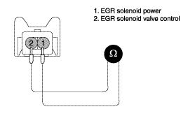
Check for open in EGR solenoid valve
(1)
Ignition "OFF".
(2)
Disconnect EGR connector.
(3)
Measure resistance between terminal 1 and 2 of EGR solenoid valve connector.
Specification : 14 ~ 17 Ω (20°C)
(4)
Is the measured resistance within specifications ?
▶ Go to "Check EGR solenoid operation" as below.
▶ Check EGR solenoid for contamination, deterioration, or damage. Substitute with a known-good EGR and check for proper operation. If the problem is corrected, replace EGR and then go to "Verification of Vehicle Repair" procedure.
2.
Check EGR solenoid valve operation
(1)
Ignition "ON" & Engine "ON".
(2)
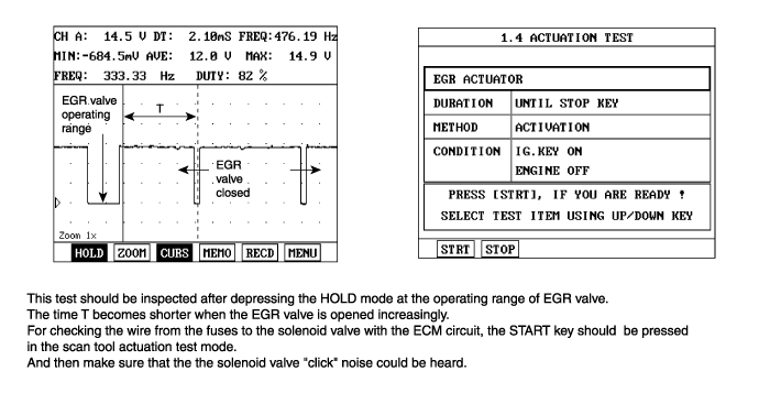
Confirm that EGR solenoid valve Duty is 5% after warming-up Engine.
(3)
Be sure that vacuum is felt after disconnecting vaccum hose from EGR solenoid valve.
(4)
Check that vacuum is felt in idle after sudden accelleration(EGR solenoid valve Duty : 95%)
EGR DUTY : 5%
EGR DUTY : 95%
No Vaccum
Vacuum
(5)
Is the vaccum felt from vaccum hose according to EGR DUTY ?
▶ Substitute with a known-good ECM and check for proper operation. If the problem is corrected, replace ECM and then go to "Verification of Vehicle Repair" procedure.
▶ Check EGR solenoid for contamination, deterioration, or damage. Substitute with a known-good EGR and check for proper operation. If the problem is corrected, replace EGR and then go to "Verification of Vehicle Repair" procedure.
VERIFICATION OF VEHICLE REPAIR
After a repair, it is essential to verify that the fault has been corrected.
1.
Connect scan tool and select "Diagnostic Trouble Codes(DTCs)" mode and then clear DTC.
2.
Operate the vehicle within DTC Enable conditions in General information.
3.
Are any DTCs present ?
Go to the applicable troubleshooting procedure.
System is performing to specification at this time.