4.
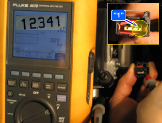
Measure voltage between terminal "1" of the CKP & CMP harness connector and chassis ground.
caution
Probe(+) : Terminal "1" of the CKP & CMP
Probe(-) : Chassis ground
A.
Specification : Approx. B+
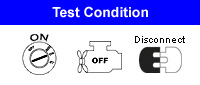
IG "OFF"
Disconnect CKP & CMP Connector.
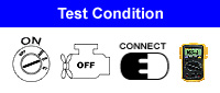
IG "ON"
Measure voltage between terminal "1" of the CKP & CMP harness connector and chassis ground.
Probe(+) : Terminal "1" of the CKP & CMP
Probe(-) : Chassis ground
Specification : Approx. B+
Is the voltage within Specification?
YES
Faulty CKP & CMP or faulty ECM
NO
Repair open or short circuit to chassis ground between CKP & CMP harness connector and control relay.
■ Inspection method of CKP & CMP power supply fuse (SNSR Fuse 10A - E/R fuse & relay box)
1. Connect a scantool to Data Link Connector(DLC).
2. IG "ON"
3. Select current data function on the scantool.
4. Check "Battery voltage" data on the scantool.
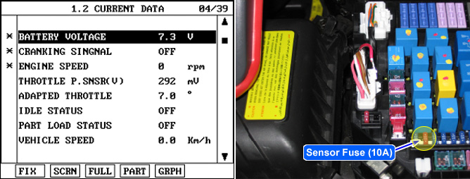
▶ If sensor fuse(10A) is open, the power isn`t supplied to terminals "14" and "21" of the ECM. So, the "BATTERY VOLTAGE" on the scantool is shown as 7.9V.
