2.
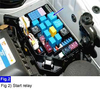
Remove the start relay from the E/R fuse & relay box.
First of all check damage of harness and terminals : Check terminals for contact resistance, corrosion and deformation.
When engine cranking is impossible although adjustment of inhibitor switch is normal, Inspect the starting system circuit.
IG KEY "OFF", ENGINE "OFF"
Remove the start relay from the E/R fuse & relay box.
Measure the voltage of the start relay terminal. (Junction box side)
Case 1 : In case that battery voltage is not supplied at terminal "5".
Repair IGN fusible link (40A) blown on the E/R fuse & relay box.
If fusible link is blown again,
- Repair short to ground in power circuit between E/R fuse & relay box connector (E06) terminal "1" and ST terminal (E53) "1".
- Repair short to ground in power circuit related with joint connector (E!8) circuit.
Case 2 : In case that battery voltage is not supplied on the terminal "2" at IG KEY "START".
Repair fuse 20 (10A) blown on the I/P junction box.
Incase of M/T,
- Repair open in relay coil power circuit between I/P relay box connector I/P-E, LHD (I/P-Ea, RHD) terminal "3 (5)" and start relay connector (E06) terminal "2".
Incase of A/T,
- Repair open in relay coil power circuit between I/P relay box connector I/P-E, LHD (I/P-Ea, RHD) terminal "3 (5)" and start relay connector (E06) terminal "2".
- Inspect the inhibitor switch.
Measure the resistance between start relay connector (E06) terminal "4" and chassis ground.
Specification : Continuity (Below 1.0 Ω)
Case 1 : In case that the resistance is high or discontinuity.
Repair open and poor connection in ground circuit between start relay connector (E06) terminal "4" and chassis ground (G06).
Measure the resistance between start relay connector (E06) terminal "1" and chassis ground.
Specification : 0.3~0.5Ω (20℃) (Pull in and Hold in coil resistance of the starter)
Case 1 : In case that the resistance is high or discontinuity.
Measure the resistance between start relay connector (E06) terminal "1" and starter terminal (ST signal) "E53".
If there is continuity, Replace the starter. (Magnetic resistance of the starter is too high.)
If there is discontinuity, Repair open in ST signal circuit between start relay connector (E06) terminal "1" and ST terminal (E53) "1".
Case 2 : In case that all terminals (Junction box side) of the start relay are normal.
Go to "Start relay inspection" procedure.
