3.
Has a problem been found?

▶ Repair as necessary and go to "Verification of Vehicle Repair" procedure.

▶ Go to "Power Supply Circuit Inspection" procedure.
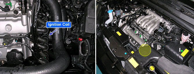
With the ignition switch in the ON or START position, voltage is applied to the ignition coil. Each ignition coil consists of two coils. High tension leads go to each cylinder from the ignition coils. The ignition coils fire two spark plugs on every power stroke (the cylinder under compression and the cylinder on the exhaust stroke). The Engine Control Module (ECM) provides a switching circuit to ground for energizing the primary ignition coils. The ECM uses the crankshaft position sensor and camshaft position sensor signal to time the energizing of the coil. When a primary ignition coil is energized and de-energized, the secondary coil produces a high voltage spike to the attached spark plugs.
The ECM monitors the peak voltage duration of the ignition primary circuit. If abnormal signal is detected on three cylinders or more, the ECM sets DTC P0350
ITEM | DETECTING CONDITION | POSSIBLE CAUSE |
Enable Conditions | ● Monitoring ignition coil primary voltage | ● Open or short in power supply circuit ● Open or short in control circuit ● Contact resistance in connectors ● Faulty ignition coil |
Threshold Value | ● Coolant temperature 〉75℃(167℉) | |
Threshold Value | ● Failure on 3 cylinder or more | |
Diagnostic Time | ● 255 revolutions |
Many malfunctions in the electrical system are caused by poor harness(es) and terminals. Faults can also be caused by interference from other electrical systems, and mechanical or chemical damage.
Thoroughly check connectors for looseness, poor connection, bending, corrosion, contamination, deterioration, or damage.
Has a problem been found?
▶ Repair as necessary and go to "Verification of Vehicle Repair" procedure.
▶ Go to "Power Supply Circuit Inspection" procedure.
Ignition "OFF".
Disconnect ignition coil connector.
Ignition "ON" & Engine "OFF".
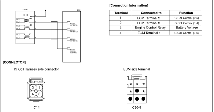
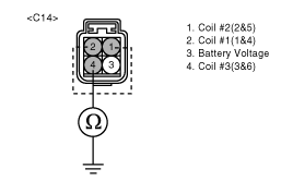
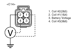
Measure voltage between terminal 3 of the coil harness connector and chassis ground.
Specification : Approx. B+
Is voltage within the specification?
▶ Go to "Control Circuit Inspection" procedure
▶ Repair as necessary and go to "Verification of Vehicle Repair" procedure.
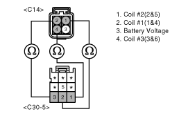
Check for open in signal harness.
Ignition "OFF".
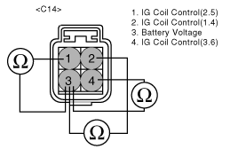
Measure resistance from each ignition coil control circuit to ECM.
Specification : Approx. 0Ω
Is resistance within the specification?
▶ Go to next step as below.
▶ Repair as necessary and go to "Verification of Vehicle Repair" procedure.
Check for short to ground in signal harness.
Measure resistance from each ignition coil control circuit (4/C14, 1/C14, 2/C14) to chassis ground.
Specification : Infinite
Is resistance within the specification?
▶ Go to next step as below.
▶ Repair as necessary and go to "Verification of Vehicle Repair" procedure.
Check for short to battery in signal harness.
Disconnect ECM connector.
Ignition "ON" & Engine "OFF".
Measure voltage from each ignition coil control circuit (4/C14, 1/C14, 2/C14) to chassis ground.
Specification : Approx. 0V
Is voltage within the specification?
▶ Go to "Component Inspection" procedure.
▶ Repair as necessary and go to "Verification of Vehicle Repair" procedure.
Ignition "OFF".
Disconnect ignition coil connector.
Visually/physically inspect the following items:
Damage, cracks and flashover.
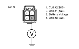
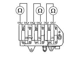
Measure the resistance in each primary coil, referring to specification.(Component side)
Specification : Approx. 0.96 ± 10% (Ω) at 20℃(68℉)
- No.1 & 4 cyl. : terminals 3 & 2
- No.2 & 5 cyl. : terminals 3 & 1
- No.3 & 6 cyl. : terminals 3 & 4
Measure the secondary coil resistance.
Measure the resistance between the high-voltage terminal for the No. 3 and No. 6 cylinders, between the high-voltage terminals for the No. 1 and No. 4 cylinders and between the high-voltage terminals for the No.2 and No.5 cylinders.
Be sure, when measuring the resistance of the secondary coil, to disconnect the connector of the ignition coil.
Specification : Approx. 12.5 ± 15% (kΩ) at 20℃(68℉)
Is resistance within the specification?
▶ Check for poor connection between ECM and component: backed out terminal, improper mating, broken locks or poor terminal to wire connection. Repair as necessary and go to "Verification of Vehicle Repair" procedure.
▶ Check ignition coil for contamination, deterioration, or damage. Substitute with a known-good ignition coil and check for proper operation. If the problem is corrected, replace ignition coil and then go to "Verification of Vehicle Repair" procedure.
After a repair, it is essential to verify that the fault has been corrected.
Connect scan tool and select "Diagnostic Trouble Codes(DTCs)" mode.
Press F4(DTAL) and confirm that "DTC Readiness Flag" indicates "Complete". If not, drive the vehicle within conditions noted in the freeze frame data or enable conditions.
Read "DTC Status" parameter.
Is parameter displayed "History(Not Present) fault"?
▶ System performing to specification at this time. Clear the DTC
▶ Go to the applicable troubleshooting procedure.
Ignition Coil | Normal Parameter at 20℃ (68℉) |
Resistance (Primary) | Approx. 0.96 ± 10% (Ω) |
Resistance (Secondary) | Approx. 12.5 ± 15% (kΩ) |
