2.
Inspect connector connection, and check terminal for poor connections, loose wires, bent, broken or corroded pins, and then verify that the connectors are always securely fastened.
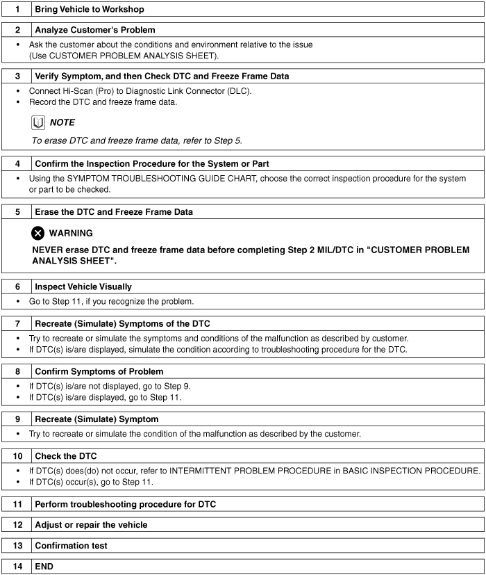
VEHICLE INFORMATION
(I) VIN: |
(II) Production Date: |
(III) Odometer Reading: ___________km |
SYMPTOMS
□ Unable to start | □ Engine does not turn over □ Incomplete combustion □ Initial combustion does not occur |
□ Difficult to start | □ Engine turns over slowly □ Other_________________ |
□ Poor idling | □ Rough idling □ Incorrect idling □ Unstable idling (High: ______ rpm, Low: ______rpm) □ Other __________________________________ |
□ Engine stall | □ Soon after starting □ After accelerator pedal depressed □ After accelerator pedal released □ During A/C ON □ Shifting from N to D-range □ Other _______________________________________________ |
□ Others | □ Poor driving (Surge) □ Knocking □ Poor fuel economy □ Back fire □ After fire □ Other ____________________________ |
ENVIRONMENT
Problem frequency | □ Constant □ Sometimes (_________________) □ Once only □ Other ___________________________________________ |
Weather | □ Fine □ Cloudy □ Rainy □ Snowy □ Other __________________ |
Outdoor temperature | Approx. _____ °C/°F |
Place | □ Highway □ Suburbs □ Inner City □ Uphill □ Downhill □ Rough road □ Other ___________________________________ |
Engine temperature | □ Cold □ Warming up □ After warming up □ Any temperature |
Engine operation | □ Starting □ Just after starting (____ min) □ Idling □ Racing □ Driving □ Constant speed □ Acceleration □ Deceleration □ A/C switch ON/OFF □ Other _____________________________ |
MIL/DTC
MIL (Malfunction Indicator Lamp) | □ Remains ON □ Sometimes lights up □ Does not light | |
DTC | Normal check (Pre-check) | □ Normal □ DTC (_______________________________________) □ Freeze Frame Data |
Check mode | □ Normal □ DTC (_______________________________________) □ Freeze Frame Data | |
The measured resistance at high temperature after vehicle running may be high or low. So all resistance must be measured at ambient temperature (20℃, 68℉), unless stated otherwise.
The measured resistance in except for ambient temperature (20℃, 68℉) is reference value.
Sometimes the most difficult case in troubleshooting is when a problem symptom occurs but does not occur again during testing. An example would be if a problem appears only when the vehicle is cold but has not appeared when warm. In this case, the technician should thoroughly make out a "CUSTOMER PROBLEM ANALYSIS SHEET" and recreate (simulate) the environment and condition which occurred when the vehicle was having the issue.
Clear Diagnostic Trouble Code (DTC).
Inspect connector connection, and check terminal for poor connections, loose wires, bent, broken or corroded pins, and then verify that the connectors are always securely fastened.
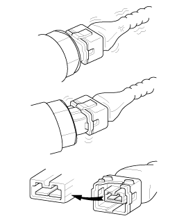
Slightly shake the connector and wiring harness vertically and horizontally.
Repair or replace the component that has a problem.
Verify that the problem has disappeared with the road test.
● SIMULATING VIBRATION
Sensors and Actuators
: Slightly vibrate sensors, actuators or relays with finger.
Strong vibration may break sensors, actuators or relays
Connectors and Harness
: Lightly shake the connector and wiring harness vertically and then horizontally.
● SIMULATING HEAT
Heat components suspected of causing the malfunction with a hair dryer or other heat source.
DO NOT heat components to the point where they may be damaged.
DO NOT heat the ECM directly.
● SIMULATING WATER SPRINKLING
Sprinkle water onto vehicle to simulate a rainy day or a high humidity condition.
DO NOT sprinkle water directly into the engine compartment or electronic components.
● SIMULATING ELECTRICAL LOAD
Turn on all electrical systems to simulate excessive electrical loads (Radios, fans, lights, rear window defogger, etc.).
Handling of Connector
Never pull on the wiring harness when disconnecting connectors.
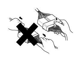
When removing the connector with a lock, press or pull locking lever.
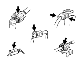
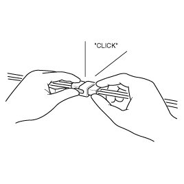
Listen for a click when locking connectors. This sound indicates that they are securely locked.
When a tester is used to check for continuity, or to measure voltage, always insert tester probe from wire harness side.
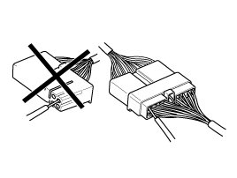
Check waterproof connector terminals from the connector side. Waterproof connectors cannot be accessed from harness side.
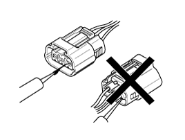
Use a fine wire to prevent damage to the terminal.
Do not damage the terminal when inserting the tester lead.
Checking Point for Connector
While the connector is connected:
Hold the connector, check connecting condition and locking efficiency.
When the connector is disconnected:
Check missed terminal, crimped terminal or broken core wire by slightly pulling the wire harness.
Visually check for rust, contamination, deformation and bend.
Check terminal tightening condition:
Insert a spare male terminal into a female terminal, and then check terminal tightening conditions.
Pull lightly on individual wires to ensure that each wire is secured in the terminal.
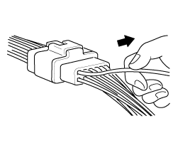
Repair Method of Connector Terminal
Clean the contact points using air gun and/or shop rag.
Never use sand paper when polishing the contact points, otherwise the contact point may be damaged.
In case of abnormal contact pressure, replace the female terminal.
Before removing the wire harness, check the wire harness position and crimping in order to restore it correctly.
Check whether the wire harness is twisted, pulled or loosened.
Check whether the temperature of the wire harness is abnormally high.
Check whether the wire harness is rotating, moving or vibrating against the sharp edge of a part.
Check the connection between the wire harness and any installed part.
If the covering of wire harness is damaged; secure, repair or replace the harness.
Procedures for Open Circuit
Continuity Check
Voltage Check
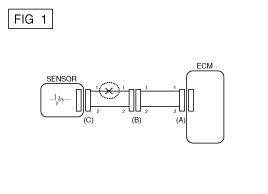
If an open circuit occurs (as seen in [FIG. 1]), it can be found by performing Step 2 (Continuity Check Method) or Step 3 (Voltage Check Method) as shown below.
Continuity Check Method
When measuring for resistance, lightly shake the wire harness above and below or from side to side.
Specification (Resistance)
1Ω or less → Normal Circuit
1㏁ or Higher → Open Circuit
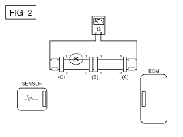
Disconnect connectors (A), (C) and measure resistance between connector (A) and (C) as shown in [FIG. 2].
In [FIG.2.] the measured resistance of line 1 and 2 is higher than 1㏁ and below 1 Ω respectively. Specifically the open circuit is line 1 (Line 2 is normal). To find exact break point, check sub line of line 1 as described in next step.
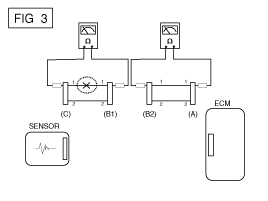
Disconnect connector (B), and measure for resistance between connector (C) and (B1) and between (B2) and (A) as shown in [FIG. 3].
In this case the measured resistance between connector (C) and (B1) is higher than 1㏁ and the open circuit is between terminal 1 of connector (C) and terminal 1 of connector (B1).
Voltage Check Method
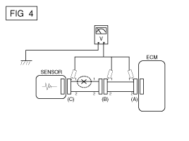
With each connector still connected, measure the voltage between the chassis ground and terminal 1 of each connectors (A), (B) and (C) as shown in [FIG. 4].
The measured voltage of each connector is 5V, 5V and 0V respectively. So the open circuit is between connector (C) and (B).
Test Method for Short to Ground Circuit
Continuity Check with Chassis Ground
If short to ground circuit occurs as shown in [FIG. 5], the broken point can be found by performing Step 2 (Continuity Check Method with Chassis Ground) as shown below.
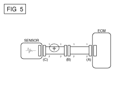
Continuity Check Method (with Chassis Ground)
Lightly shake the wire harness above and below, or from side to side when measuring the resistance.
Specification (Resistance)
1Ω or less → Short to Ground Circuit
1MΩ or Higher → Normal Circuit
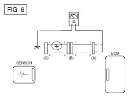
Disconnect connectors (A), (C) and measure for resistance between connector (A) and Chassis Ground as shown in [FIG. 6].
The measured resistance of line 1 and 2 in this example is below 1 Ω and higher than 1MΩ respectively. Specifically the short to ground circuit is line 1 (Line 2 is normal). To find exact broken point, check the sub line of line 1 as described in the following step.
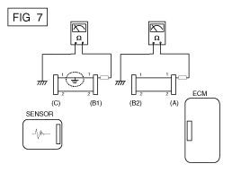
Disconnect connector (B), and measure the resistance between connector (A) and chassis ground, and between (B1) and chassis ground as shown in [FIG. 7].
The measured resistance between connector (B1) and chassis ground is 1Ω or less. The short to ground circuit is between terminal 1 of connector (C) and terminal 1 of connector (B1).
Possible Cause | |
● Run out of fuel ● Starter faulty ● Fuel pump hose supply cut ● High pressure leakage ● Fuse out of order ● Drift of the rail pressure sensor not detected ● Cam and Crank signals missing simultaneously ● Battery voltage too low ● Faulty immobilizer ● Electric EGR control valve blocked open ● Fuel pressure regulator valve contaminated, stuck, jammed ● Rail pressure regulator valve contaminated, stuck, jammed ● Fuel quality / presence of water | ● Inversion of low pressure fuel connections ● Fuel filter not adapted ● Low pressure fuel circuit sealed ● Sealed fuel filter ● Intermittent fault connection ● Air ingress in the low pressure fuel circuit ● Fuel return circuit of the pump sealed ● Engine compression too low ● Leakage at the injector ● Low pressure fuel pump faulty ● High pressure fuel pump faulty ● Injector jammed open ● Bug software or hardware fault not detected ● Glow system faulty |
Possible Cause | |
● Run out of fuel ● Fuel return hose of injector cut ● High pressure leakage ● Fuse faulty ● Air filter sealed ● Alternator or voltage regulator faulty ● The compensation of individual injector not adapted ● Drift of the engine coolant temperature sensor not detected ● Drift of the rail pressure sensor not detected ● Battery voltage too low ● Electric EGR control valve blocked open ● Fuel pressure regulator valve contaminated, stuck, jammed ● Rail pressure regulator valve contaminated, stuck, jammed ● Fuel quality / presence of water | ● Inversion of low pressure fuel connections ● Low pressure fuel circuit sealed ● Sealed fuel filter ● Oil level too high/too low ● Catalytic converter sealed or damaged ● Intermittent fault connection ● Air ingress in the low pressure fuel circuit ● Fuel return circuit of the pump sealed ● Glow system faulty ● Engine compression too low ● Fuel return hose of injector sealed ● Carbon deposit on the injector (sealed holes) ● Needle stuck (injection possible over a certain pressure) ● Gasoline in fuel ● Bug software or hardware fault not detected |
Possible Cause | |
● The compensation of individual injector not adapted ● Drift of the rail pressure sensor not detected ● Electric EGR control valve blocked open ● Fuel pressure regulator valve contaminated, stuck, jammed ● Rail pressure regulator valve contaminated, stuck, jammed ● Air filter sealed ● Air ingress in the low pressure fuel circuit ● Fuel quality / presence of water | ● Fuel return circuit of the pump sealed ● Sealed fuel filter ● Engine compression too low ● Intermittent fault connection ● Carbon deposit on the injector (sealed holes) ● Needle stuck (injection possible over a certain pressure) ● Gasoline in fuel ● Bug software or hardware fault not detected |
Possible Cause | |
● Fuel return hose of injector cut ● The compensation of individual injector not adapted ● Drift of the rail pressure sensor not detected ● Harness resistance increased ● Air ingress in the low pressure fuel circuit ● Fuel quality / presence of water ● Sealed fuel filter ● Air filter sealed ● Fuel return hose of injector sealed ● High pressure leakage | ● Glow system faulty ● Engine compression too low ● Bad flanging of the injector ● High pressure pump out of order ● Injector not adapted ● Carbon deposit on the injector (sealed holes) ● Needle stuck (injection possible over a certain pressure) ● Injector jammed open ● Electric EGR control valve blocked open |
Possible Cause | |
● Drift of the engine coolant temperature sensor not detected ● Incorrect state of the electrical pack devices ● Alternator or voltage regulator faulty | ● Clutch not well set ● Bug software or hardware fault not detected ● Electric EGR control valve blocked open ● Throttle control actuator faulty |
Possible Cause | |
● The compensation of individual injector not adapted ● Drift of the engine coolant temperature sensor not detected ● Drift of the rail pressure sensor not detected ● Electric EGR control valve blocked open ● Fuel pressure regulator valve contaminated, stuck, jammed ● Rail pressure regulator valve contaminated, stuck, jammed ● Oil level too high/too low ● Fuel quality / presence of water | ● Catalytic converter sealed or damaged ● Air filter sealed ● Oil suction (engine racing) ● Glow system faulty ● Engine compression too low ● Bad flanging of the injector ● Injector washer not adapted, forgotten, doubled ● Injector not adapted ● Carbon deposit on the injector (sealed holes) ● Injector jammed open ● Gasoline in fuel |
Possible Cause | |
● The compensation of individual injector not adapted ● Electric EGR control valve blocked closed (noisy engine) ● Electric EGR control valve blocked open ● Drift of the engine coolant temperature sensor not detected ● Glow system faulty ● Engine compression too low ● Fuel return hose of injector sealed | ● Drift of the rail pressure sensor not detected ● Injector washer not adapted, forgotten, doubled ● Injector not adapted ● Carbon deposit on the injector (sealed holes) ● Needle stuck (injection possible over a certain pressure) ● Injector jammed open ● Drift of engine coolant temperature sensor not detected |
Possible Cause | |
● The compensation of individual injector not adapted ● Intermittent fault connection ● Exhaust system sealed ● Drift of the rail pressure sensor not detected | ● Fuel pressure regulator valve contaminated, stuck, jammed ● Rail pressure regulator valve contaminated, stuck, jammed ● Bug software or hardware fault not detected |
Possible Cause | |
● Accelerator position sensor blocked ● Electric EGR valve blocked open ● Intermittent fault connection | ● Oil suction (engine racing) ● Drift of the rail pressure sensor not detected ● Bug software or hardware fault not detected |
Possible Cause | |
● Air inlet circuit open ● Incorrect state of the electrical pack devices ● Accelerator position sensor blocked ● Electric EGR valve blocked open ● Turbo charger damaged, vacuum hose line leakage ● Sealed fuel filter | ● Engine compression too low ● High pressure leakage ● Fuel pressure regulator valve contaminated, stuck, jammed ● Rail pressure regulator valve contaminated, stuck, jammed ● Needle stuck (injection possible over a certain pressure) ● Bug software or hardware fault not detected |
Possible Cause | |
● Run out of fuel ● Fuel pump hose supply cut ● High pressure leakage ● Fuse faulty ● Fuel quality / presence of water ● Low pressure fuel circuit sealed ● Sealed fuel filter ● Crank signals missing simultaneously ● Electric EGR valve blocked open ● Fuel pressure regulator valve contaminated, stuck, jammed | ● Rail pressure regulator valve contaminated, stuck, jammed ● Alternator or voltage regulator faulty ● Intermittent fault connection ● Catalytic converter sealed or damaged ● Oil suction (engine racing) ● Low pressure fuel pump faulty ● High pressure pump faulty ● Faulty ignition key ● Gasoline in fuel ● Bug software or hardware fault not detected |
Possible Cause | |
● Run out of fuel ● Fuel return hose of injector cut ● Incorrect state of the electrical pack devices ● The compensation of individual injector not adapted ● Electric EGR valve blocked open ● Fuel filter not adapted ● Air ingress in the low pressure fuel circuit ● Fuel quality / presence of water ● Sealed fuel filter ● Intermittent fault connection ● Harness resistance increased | ● Glow system faulty ● Engine compression too low ● Fuel return hose of injector sealed ● Valve clearance ● Low pressure fuel pump faulty ● Injector washer not adapted, forgotten, doubled ● Carbon deposit on the injector (sealed holes) ● Needle stuck (injection possible over a certain pressure) ● Injector jammed open ● Gasoline in fuel ● Bug software or hardware fault not detected |
Possible Cause | |
● The compensation of individual injector not adapted ● Accelerator position sensor blocked ● Incorrect state of the electrical pack devices ● Electric EGR valve blocked open ● Air inlet circuit open ● Air filter sealed ● Oil level too high/too low ● Catalytic converter sealed or damaged ● Turbo charger damaged, vacuum hose line leakage | ● Sealed fuel filter ● Leakage at the injector ● Fuel return circuit of the pump sealed ● Fuel return hose of injector sealed ● Engine compression too low ● Injector not adapted ● Carbon deposit on the injector (sealed holes) ● Valve clearance |
Possible Cause | |
● The compensation of individual injector not adapted ● Oil suction (engine racing) | ● Bug software or hardware fault not detected |
Possible Cause | |
● Fuel return hose of injector cut ● Leakage at the Fuel pressure regulator valve ● Leakage at fuel temperature sensor ● Leakage at the spacers ● High pressure leakage ● Air inlet circuit open ● Air filter sealed ● The compensation of individual injector not adapted ● Electric EGR valve blocked open | ● Incorrect state of the electrical pack devices ● Oil level too high/too low ● Fuel quality / presence of water ● Catalytic converter sealed or damaged ● Turbo charger damaged ● Engine compression too low ● Injector not adapted ● Bug software or hardware fault not detected |
Possible Cause | |
● Accelerator position sensor blocked ● The compensation of individual injector not adapted ● Intermittent fault connection ● Clutch not well set | ● Oil suction (engine racing) ● Turbo charger damaged ● Injector not adapted ● Bug software or hardware fault not detected |
Possible Cause | |
● Electric EGR control valve leakage ● Oil suction (engine racing) ● Turbo charger damaged ● Oil level too high/too low ● The compensation of individual injector not adapted ● Catalytic converter sealed or damaged ● Bad flanging of the injector | ● Injector washer not adapted, forgotten, doubled ● Injector not adapted ● Carbon deposit on the injector (sealed holes) ● Needle stuck (injection possible over a certain pressure) ● Injector jammed open ● Bug software or hardware fault not detected |
Possible Cause | |
● The compensation of individual injector not adapted ● Electric EGR valve blocked open ● Air filter sealed ● Fuel quality / presence of water ● Oil level too high/too low ● Turbo charger damaged ● Catalytic converter sealed or damaged ● Oil suction (engine racing) ● Air heaters out of order ● Engine compression too low ● High pressure leakage | ● Intermittent fault connection ● Bad flanging of the injector ● Injector washer not adapted, forgotten, doubled ● Injector not adapted ● Carbon deposit on the injector (sealed holes) ● Needle stuck (injection possible over a certain pressure) ● Injector jammed open ● Gasoline in fuel ● Bug software or hardware fault not detected ● Catalyzed Particulate Filter (CPF) fail |
Possible Cause | |
● Fuel pump hose supply cut ● Fuel return hose of injector cut ● Leakage at the Fuel pressure regulator valve | ● Leakage at fuel temperature sensor ● Leakage at the spacers ● High pressure leakage |
Possible Cause | |
● Accelerator position sensor blocked ● Incorrect state of the electrical pack devices ● Air filter sealed ● Inversion of low pressure fuel connections ● Fuel filter not adapted ● Fuel quality/presence of water ● Air ingress in the low pressure fuel circuit ● Sealed fuel filter | ● Catalytic converter sealed or damaged ● Clutch not well set ● Intermittent fault connection ● Drift of the rail pressure sensor not detected ● Fuel pressure regulator valve contaminated, stuck, jammed ● Rail pressure regulator valve contaminated, stuck, jammed ● Gasoline in fuel ● Bug software or hardware fault not detected |
Possible Cause | |
● Faulty ignition key ● Oil suction (engine racing) ● Bug software or hardware fault not detected |
Possible Cause | |
● Buzzer noise (discharge by the injectors) ● Clip broken (vibrations, resonance, noises) ● Incorrect state of the electrical pack devices ● Catalytic converter sealed or damaged ● Air inlet circuit open | ● Bad flanging of the injector ● Clutch not well set ● Turbo charger damagedValve clearance ● Valve clearance |

