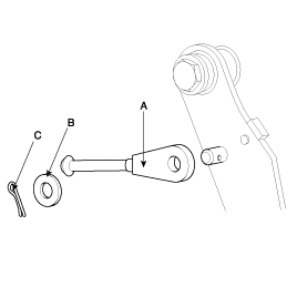
Remove the clutch master cylinder connecting rod (A), washer (B), and split pin (C).

Remove the clutch master cylinder connecting rod (A), washer (B), and split pin (C).

Remove the clutch pedal mounting bolts.
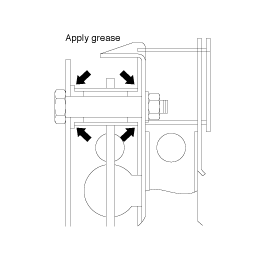
Apply the specified grease to the clutch pedal and bushings.
Chassis grease: SAE J310a, NLGI No.1
Install the clutch pedal mounting bolt.

Apply the specified grease to the clevis pin and washer.
Wheel bearing grease: SAE J310, NLGI No.2
Install the push rod to the clutch pedal.
Check the pedal shaft and bushing for wear.
Check the clutch pedal for bending or torsion.
Check the return spring for damage or deterioration.
Check the pedal pad for damage or wear.


Deformation of pedal pad must be MAX. 5mm after repeating the test 20 times (sudden return from full stroke).
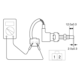
Check for the ignition lock switch.
In case of clutch lock system vehicle, there is an additiond switch.
Before adjusting, remove the driver's floor seat.
After loosening the ignition lock switch nut, move it back until it has no contact with the clutch pedal arm.(In case of clutch lock system vehicle, repeat this step with its additional ignition lock switch).
Check for the specification below.
Clutch pedal stroke : 150 mm
Clutch pedal free play : 13 mm or less
Distance between the inner pad and clutch pedal : 250 ~ 254 mm
Fix the ignition switch whtn its signal is OFF pressing the pedal slowly (52 ~ 58 mm).
Tighten the fixing nut with specification
TORQUE : 8~ 10 Nm (80 ~ 100 kgf·cm, 5.9 ~ 7.4 lbf·ft)
(Clutch lock system vehicle)
Fix the additional ignition lock switch when its signal is ON pressing the pedal slowly (117 ~ 123 mm).
Tighten the fixing nut with specification.