
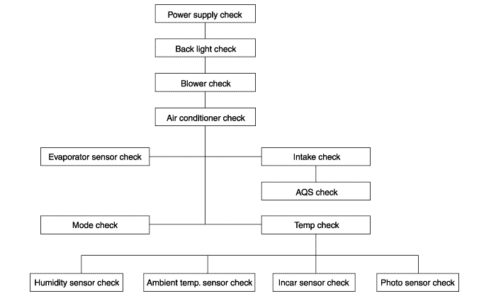
Power supply check
Back light check
Blower check
Air conditioner check
Intake check and AQS check
Mode check
Temp check
Sensor check
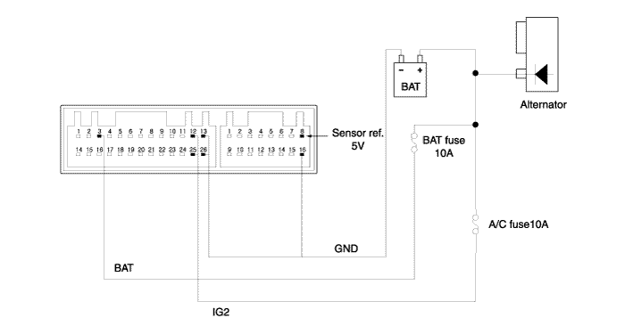
In turning off IGN, battery supplies power for ordinary power, FATC connector A3 through battery fuse. FATC performs memory function by means of battery power supplied as described above. In turning on IGN, alternator is driven. At this time, IG2 power generated in alternator FATC connector A12 and A25 terminal through IG2 fuse and air conditioner fuse 10A. FAT carried out actual system operation by means of IG2 power supplied as described above.
Symptoms | Causes | How to check |
When IG is ON, memory function error occurs | Battery power supply error | Check voltage of battery after turning off IG. If 10V and more, check FATC connector and if no problem, check the inside of controller. If 10V and less, check fuse or wiring state of battery power source. |
When IG is ON, system running error occurs | IG2 power supply error | Check voltage of IG2 after turning on IG. If 10V and more, check FATC connector and if no problem, check the inside of controller. If 10V and less, check fuse or wiring state of IG2 power source. |
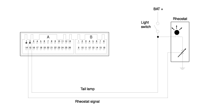
In turning on IG and then light switch, battery power is supplied for FATC connector A2 terminal through wiring. The supplied power passes connector A1 terminal through light bulb in FATC and flows into reostart as shown in the above figure. The brightness is adjusted according to resistance value of reostart.
Symptoms | Causes | How to check |
When light switch is ON, partial error occurs in back light | Light bulb lighting error in FATC | |
When light switch is ON, entire error occurs in back light | Light power supply error | Measure voltage of tail light shown in the above figure after switching on light. If 10V and more, check FATC connector and if no problem, measure signal voltage of reostart shown in the above figure. If 8V and more, check reostart wiring and reostart. |
If tail light is below 1V, check tail light wiring. |
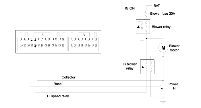
Perform the blower check in manual blower running state because it is difficult to check blower at automatic control. Blower is controlled from level l to level 8 equally as in button operation and running logic. In turning on IG, blower relay is ON and voltage of 0.1 to 1.4V is transferred from FATC connector A4 terminal to base source of power TR according to FATC control (selectable from level 1 to level 8). At this time, voltage of blower motor's both ends is determined according to collector voltage of FATC connector A5 terminal. If FATC is controlled in level 8, GND(0V) is supplied for FATC connector A18 terminal and high blower relay is driven.
Symptoms | Causes | How to check |
Amount of wind is wrong at manual selection of blower | Power TR error | Check voltage of blower motor's both ends. (Level 1: 3.8V, Level 2: 5.2V, Level 3: 6.5V, Level 4: 7.9V, Level 5: 9.2V, Level 6: 10.6V, Level 7: 12.0V, Level 8: 13.5V [high-relay operation]) Measure voltage of each terminal and if there is difference more than ±0.6V, check power TR. |
Blower wind is discharged despite pressing OFF switch | Power TR error | Power TR change |
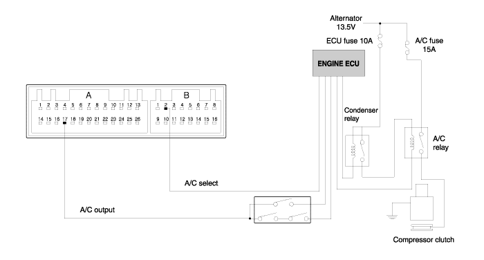
11V is outputted from connector A17 terminal in turning on INSULATING and pressing air conditioner switch. However, although 11V is outputted from FATC connector A17 terminal, compressor clutch isn't driven. Wind of air conditioner is discharged if only compressor clutch works. Output signal from air conditioner is inputted in engine computer through triple switch. Then, the engine computer considers several conditions and when output of air conditioneris judged to be practical, it gives GND to signal terminal of air conditioner relay. Accordingly, relay of air conditioner is ON and compressor clutch works. Triple switch checks pressure of refrigerant flowing through pipe and turns on/off switches in it according to standard. So, it controls that output signalof air conditioner outputted from FATC is inputted into engine computer, and also speed of condenser fan according to pressure level. (For high pressure, high-speed and for low pressure, low-speed.
Symptoms | Causes | How to check |
Wind of air conditioner isn't discharged into vehicle despite switching on air conditioner. | Signal output error of air conditioner | Switch on air conditioner and measure voltage of FATC connector A17 terminal as shown in the above figure. If 9V and more, check triple switch,air conditioner relay and ECM. |
Switch on air conditioner and measure voltage of FATC connector A17 terminal as shown in the above figure. If 1V and less, check input value ofevaporator sensor. | ||
Input error of evaporator sensor | If evaporator sensor is disconnected or short or voltage of its inputsource is more than 3.0V (below 0.5°C), output of air conditioner isn't made. |
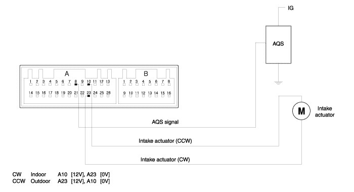
In turning on IG and selecting indoor mode with indoor switch, 12V is outputted from FATC connector A23 terminal, 0V is supplied for A10 terminaland motor works in direction of outdoor. In selecting outdoor mode with indoorswitch, 12V is outputted from FATC connector A10 terminal, 0V is supplied for A23 terminal and motor works in direction of indoor.
Symptoms | Causes | How to check |
Indoor mode running error | Power supply error in actuator | Separate connector linked with actuator, select indoor mode with indoor switch and measure voltage of FATC connector A23 terminal. If 8V and more, check actuator or wiring state and if 9V and less, check the inside of controller. |
Outdoor mode running error | Power supply error in actuator | Select outdoor mode in the above method and measure voltage of FATC connector A10 terminal. If 8V and more, check actuator or wiring state and if 9V andless, check the inside of controller |
Fixed in outdoor or indoor mode at AQS selection | AQS signal terminal output error | Select AQS switch and measure AQS signal terminal as shown in the above figure. If there is no change of voltage over 10 min, check AQS. |
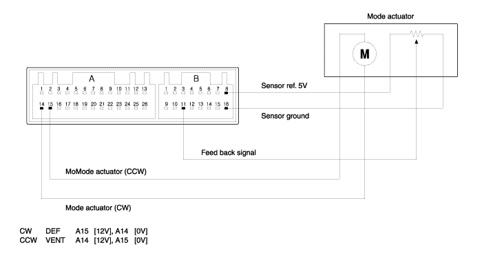
In turning on IG and selecting mode switch, sequential operation begins in order of Vent → Bi-level → Blower → Mix. DIP mode works regardless of order at selecting it. As shown in the above figure, in adjusting mode switch from VENT to DEF, 12V is outputted from connector B4, 0V is supplied for B5 and mode motor works in direction of DEF. In adjusting mode switch from DEF to VENT, 12V is outputted from connector B5, 0V is supplied for B4 and mode motor works in direction of VENT. When mode actuator has to move to a certain location for its automatic control, mode feedback signal terminal moves equally in mode actuator and informs controller of location of mode actuator through mode connector B6. Comparing original value with the inputted value, it works until they are same.
Symptoms | Causes | How to check |
Mode actuator running error | Power supply error in mode actuator | After altering VENT to DEF, measure voltage of connector A15, and after altering DEF to VENT, measure voltage of connector A14. It both of them are 9V and move, check mode actuator an peripheral wiring state and if one or both of them are 9V and less, its cause is internal failure of control. |
Sensor(+5) power supply error | If automatic control isn't operated smoothly, measure voltage of FATC connector B8 terminal, If under 4.8V or over 5.2V, its cause is internal failure of FATC. | |
Driver error of mode actuator | If NO.22 is outputted as result of self-diagnostic, check mode actuator driver. |
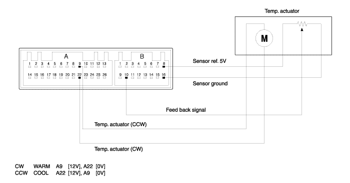
In adjusting temp switch from 32°C to 17°C, 12V is outputted from FATC connector A22 terminal, 0V is supplied for A9 terminal and temp motor works in direction of COOL. In adjusting temp switch from 17°C to 32°C, 11V is outputted from FATC connector A9 terminal, 0V is supplied for A22 terminal and temp motor works in direction of WARM. When temp actuator has to move to a certain location for its automatic control, temp feedback signal terminal moves equally in temp actuator and informs controller of location of temp actuator through FATC connector B10 terminal. Comparing original value with inputted value, it works until they are same. If 4.9V and more is inputted in B10 terminal, it is regarded as disconnection. If 0.1V and less is inputted in B10 terminal, it is regarded as short-circuit. In the case of disconnection or short-circuit as a result of self-diagnostic, substitute control is carried out as follows.
If setup temperature is 17°C to 24.5°C, set to MAX COOL.
If setup temperature is 25°C to 32.0°C, set to MAX WARM.
Symptoms | Causes | How to check |
Temp actuator running error | Power supply error in temp actuator | After altering 17°C to 32°C and adversely, measure voltage of A9 and after altering 32°C to 17°C and adversely, measure voltage of A22. If Both of them are 9V and more, check temp actuator and peripheral wiring state and if one or both of them are 5V and less, its cause is internal failure of FATC. |
Sensor (+5) power supply error | If automatic control isn't operated smoothly, measure voltage of FATC connector B8 terminal. If under 4.8V or over 5.2V, its cause is internal failure of FATC. | |
Driver error of temp actuator | If No. 20 is outputted as a result of self-diagnostic, check temp actuatordriver. |
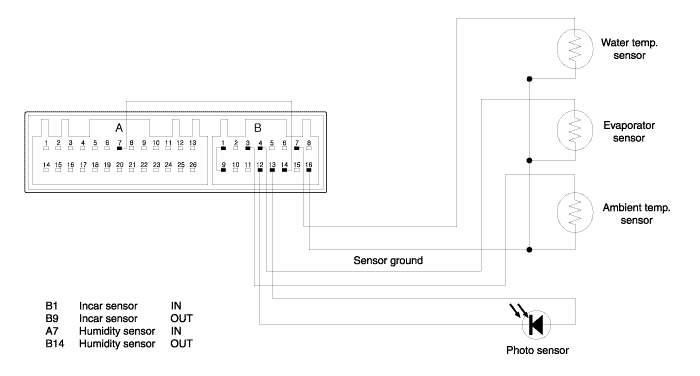
Resistance value set according to temperature of each part is inputted in FATC controller.
Internal temperature of vehic is automatically controlled by operating the inputted values.
It is recommended to refer to resistance value and voltage value corresponding to each temperature and the followings explains essential functions of each sensor required for repair and self-diagnostics and substitute functions at disconnection or short-circuit.
If 4.9V and more is inputted in connectors B1, B3, B4, B7, B12 terminal, it is regarded as disconnection.
If 0.1V and less is inputted in connectors B1, B3, B4, B7, B12 terminal, it is regarded as short-circuit.