COMPONENT LOCATION
GENERAL DESCRIPTION

Refer to DTC P1750.

DTC DESCRIPTION

Refer to DTC P1750.

DTC DETECTING CONDITION

Refer to DTC P1750.

SCHEMATIC DIAGRAM
WAVEFORM INSPECTION

Refer to DTC P1750.

TERMINAL & CONNECTOR INSPECTION
1.

Many malfunctions in the electrical system may be caused from poor harness and terminals. These faults can be caused by interference from other electrical systems and mechanical or chemical damage.

2.

Thoroughly check connectors for looseness, poor connection, bending, corrosion, contamination, deterioration, or damage.

Has a problem been found?

▶ Repair as necessary and go to "Verification of Vehicle Repair" procedure.

▶ Go to the next procedure.

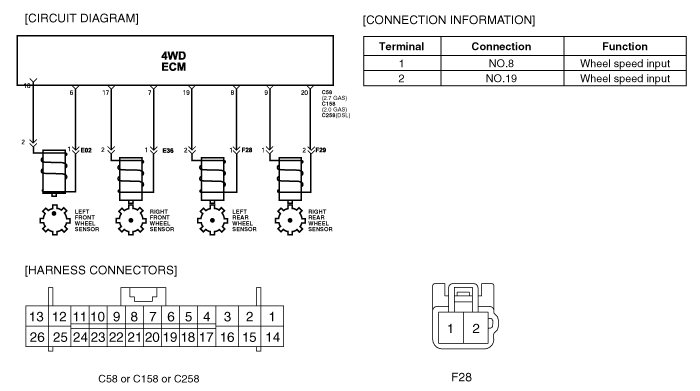
SIGNAL CIRCUIT INSPECTION
1.

RLSS(Rear Left Speed Sensor) Signal Inspection

(1)

IG KEY ON, ENG ON

(2)

4WD ECM connector : Connect.

(3)

Monitor signal waveform between terminal 19 of 4WD ECM harness connector and chassis ground.

(4)

Start and drive vehicle in gear and maintain vehicle speed is approx. 10km/h or less(6mph or less).

Specification : refer to 'Waveform Inspection'

Is RLSS Signal display near the specified value?

▶ This may caused by intermittent fault. Verify data changibility by shaking the harness.

▶ Inspect ground to short of RLSS circuit.

▶ Inspect open or short of RLSS circuit.

▶ Check for RLSS and replace it as necessary.

▶ Check for 4WD ECM and replace it as necessary.

2.

RLSS open inspection

(1)

IG KEY OFF, ENG OFF

(2)

4WD ECM connector and RLSS connector : Disconnect.

(3)

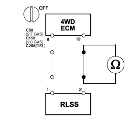
Measure resistance between terminal 19 of 4WD ECM harness connector and terminal 2 of RLSS harness connector.

Specification : Approx. 0Ω

Is resistance display near the specified value?

▶ Proceed next inspection procedure.

▶ Repair open circuit of RLSS circuit.

▶ If problem is solved, go to the "Verification of Vehicle Repair".

3.

RLSS ground circuit open inspection

(1)

IG KEY OFF, ENG OFF

(2)

4WD ECM connector and RLSS connector : Disconnect.

(3)

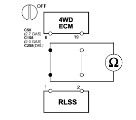
Measure resistance between terminal 8 of 4WD ECM harness connector and terminal 1 of RLSS harness connector.

Specification : Approx. 0Ω

Is resistance display near the specified value?

▶ Proceed next inspection procedure.

▶ Repair open circuit of RLSS circuit.

▶ If problem is solved, go to the "Verification of Vehicle Repair".

Ground Circuit Inspection
1.

RLSS short to ground inspection

(1)

IG KEY OFF, ENG OFF

(2)

4WD ECM connector and RLSS connector : Disconnect.

(3)

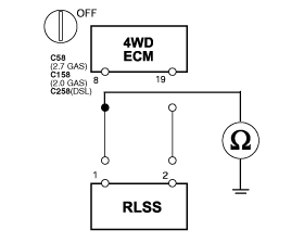
Measure resistance between terminal 19 of 4WD ECM harness connector and chassis ground.

Specification : Approx. ∞Ω

Is resistance display near the specified value?

▶ Proceed next inspection procedure.

▶ Repair ground to short circuit of RLSS circuit.

▶ If problem is solved, go to the "Verification of Vehicle Repair".

Visual/Physical Inspection
1.

RLSS Air Gap Inspection

(1)

IG KEY : OFF, Engine : OFF.

(2)

4WD ECM connector and RLSS connector : Disconnect.

(3)

Measure air gap between wheel speed sensor and rotor.

Specification : Front Air-gap : 0.3~0.9mm (0.0118 ~ 0.0354 inch)

Is the air gap in the range of the specified value?

▶ Replace with normal TCCU temporarily and check if vehicle run normally.

If trouble is disappeared, replace TCCU.

▶ If problem is solved, go to the "Verification of Vehicle Repair".

▶ Adjust the air gap.

▶ If problem is solved, go to the "Verification of Vehicle Repair".

Component Inspection
1.

IG KEY : OFF, Engine : OFF

2.

4WD ECM connector and RLSS connector : Disconnect.

3.

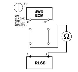
Measure resistance between terminal 1 & 2 of RLSS harness connector.

Specification : Approx. 1.1 ± 0.05㏀

note

The above value is just for reference. The data from vehicle may differ from it according as various vehicle condition. This inspection is for checking open or short of RLSS.

Is resistance display near the specified value?

▶ Proceed next inspection procedure.

▶ Replace the front left speed sensor.

▶ If problem is solved, go to the "Verification of Vehicle Repair".

VERIFICATION OF VEHICLE REPAIR
1.

IG KEY ON, ENG ON

2.

4WD ECM connector and RLSS connector : Connect.

3.

Clear the DTC with a scan tool.

4.

Start and drive vehicle in gear and maintain vehicle speed is approx. 10km/h or less(6mph or less).

5.

Check RLSS signal signal and verify the malfunction.

Does the scan tool display any DTC relevent to RLSS signal?

Go to the applicable troubleshooting procedure.

▶ System OK.

Яндекс.Метрика